The signals may be in a variety of different forms depending on what equpiment you may have bought, and other circuits you may have made from these pages or from other sources:
This page describes several converter circuits for converting between the most common formats. Note that the conversions here do not relate directly to steering of the robot. The direction referred to relates to the rotational direction of a motor, not to the direction steered by the motor (although of course it does affect the steering of the robot).
If you are interested in a converter to change two servo channels for robot speed and robot direction (steering) into two PWM signals for driving the left and right motors, see the steering mixer page.
Signal |
Form |
| Speed | [1] Analogue value (0 - 5v) for whole robot |
| [2] Analogue value (0 - 5v) for one motor | |
| [3] Servo signal for whole robot | |
| [4] Servo signal for one motor | |
| [5] PWM signal for one motor | |
| Speed and motor direction | [6] Single servo signal |
| Motor Direction | [7] Digital (backwards / forwards) |
| [8] Single servo signal |
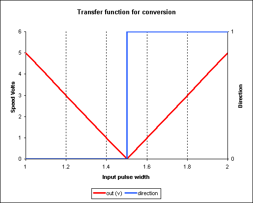
A table and graph can be drawn of the required conversion:
| Input pulse from RC receiver | Analogue speed signal | Digital direction signal | |
| (0 to 5v) | PWM ratio | ||
| 1 ms | 5 v | 100% | 0 |
| 1.2 ms | 3 v | 60% | 0 |
| 1.4 ms | 1 v | 20% | 0 |
| 1.5ms | 0 v | 0% | X |
| 1.6 ms | 1 v | 20% | 1 |
| 1.8 ms | 3 v | 60% | 1 |
| 2.0 ms | 5 v | 100% | 1 |
A block diagram of a system for generating this conversion is shown below:
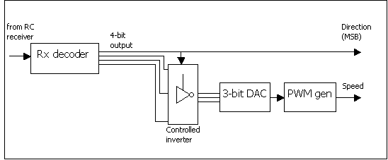
The signal is first decoded to a 4-bit word using the digital receiver decoder circuit presented in the Rx Decoder page. The most signficant bit of this is the direction signal, which is a digital signal that changes state half way through the range of values from the Rx decoder. This is used to optionally invert the remaining three bits, inverting them when it is 0 and leaving them unchanged when it is 1. Inverting these is effectively negating the 3-bit value of them. It is this that causes the ‘V’ shape in the required graph. The input and output values of these 4 bits are as follows:
| Pulse width (ms) | Rx decoder output | Output from XOR gates | Value of output |
| 1 | 0 000 | 111 | 7 |
| 1.0625 | 0 001 | 111 | 7 |
| 1.125 | 0 010 | 110 | 6 |
| 1.1875 | 0 011 | 101 | 5 |
| 1.25 | 0 100 | 100 | 4 |
| 1.3125 | 0 101 | 011 | 3 |
| 1.375 | 0 110 | 010 | 2 |
| 1.4375 | 0 111 | 001 | 1 |
| 1.5 | 1 000 | 000 | 0 |
| 1.5625 | 1 001 | 001 | 1 |
| 1.625 | 1 010 | 010 | 2 |
| 1.6875 | 1 011 | 011 | 3 |
| 1.75 | 1 100 | 100 | 4 |
| 1.8125 | 1 101 | 101 | 5 |
| 1.875 | 1 110 | 110 | 6 |
| 1.9375 | 1 111 | 111 | 7 |
| 2 | 1 111 | 111 | 7 |
The DAC can be just a simple weighted resistor ladder into an opamp summing junction. This can generate the required output voltage between 0 and 5v. Note that since this is a digital circuit, the V characteristic will be stepped rather than smooth as in the graph above, but this won’t matter much for speed control – it will be barely noticeable. If necessary, the 0-5v signal can be inputted to a PWM generator circuit to generate a PWM waveform for the speed signal.
The complete circuit diagram (except for the digital RxDecoder and PWM generator which are shown elsewhere) is shown below:
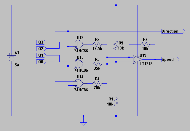
Click on the circuit diagram to open it in a new window.
A SPICE simulation of the circuit is shown below which confirms its required operation.
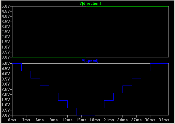
The XOR gates conditionally invert the Q0..Q2 signals when Q3 is high, that is when the receiver pulse width is between 1.5ms and 2ms. Otherwise, for receiver pulse widths between 1.0ms and 1.5ms, Q0..Q2 are left un-inverted. The outputs of the three XOR gates are fed into a DAC, which is implemented as a simple adder circuit. This sums a +5v signal and the negative of the three inputs according to the following gains:
| Input | Gain |
| Q2 | 4/7 |
| Q1 | 2/7 |
| Q0 | 1/7 |
The output voltage is then given by the equation:
Vout = 5 – (4/7·VQ2 + 2/7·VQ1 + 1/7·VQ0)
Note that the opamp must be a rail-to-rail type for inputs and output to be able to accept inputs in the range 0 to 5v, and to be able to output 0v - 5v. Given the inputs are logic 0-5v, the output voltage, depending on the input code of Q2..Q0, is:
| Q2.Q1.Q0 | Q Value | Output voltage |
| 000 | 0 | 0.00v |
| 001 | 1 | 0.72v |
| 010 | 2 | 1.43v |
| 011 | 3 | 2.15v |
| 100 | 4 | 2.85v |
| 101 | 5 | 3.57 |
| 110 | 6 | 4.28v |
| 111 | 7 | 5.00v |
As explained previously, the output is stepped because of the digital nature of the input pulse width measurement.
| Manufacturer | Device |
| Linear Technology | LT1218 rail-to-rail opamp |
74HC86 Quad XOR gate |
The Team Delta R/C to 4QD Interface sits between the RC receiver and a 4QD
speed controller, performing the necesary conversion:
http://www.teamdelta.com/products/prod2a.htm