A typical fighting robot consists of a powerful main battery powering motors via a speed controller, and a radio control receiver which controls the speed controller. The radio control receiver also needs its own battery to power it. A battery eliminator circuit (BEC) eliminates the need for the radio control receiver's battery, by powering it from the main battery. This has the advantage of removing one battery from the robot, but has the potential to reduce or even destroy the effectiveness of the radio control system.
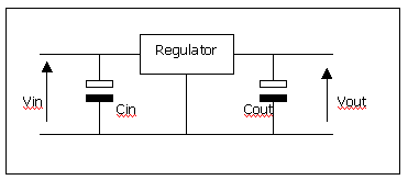
A BEC circuit is typically just a voltage regulator which convertes the 12V or higher voltage of the main battery down to the (typically) 5V required by the radio control receiver. These voltage regulators are cheap off-the-shelf electronic components. They generally have three terminals, an input voltage, a 0V reference pin, and the output voltage.
The capacitors either side of the regulator smooth out any ripples in the voltages. The capacitor to the right is an integral part of the regulator's feedback circuit as we shall see.
So what is inside one of these regulators. A simplified circuit diagram is shown below:

On the right hand side, a reference voltage is produced using (in this case) a zener diode. This voltage is compared with a sample of the output voltage produced by the resistor potential divider. If the sample output voltage is greater than the reference voltage, then the opamp increases the voltage at the base of the pass transistor, and the transistor turns off a little, thereby dropping more voltage across it, and leaving less voltage on the right hand side of it. Therefore the circuit will correct itself if the output voltage increases above the required voltage. Conversely, if the output voltage drops a bit, the opamp's output will decrease and the pass transistor will turn on a bit more, thereby increasing the output voltage again.
In any negative feedback loop like this, there is an issue of stability. The subject of stability is covered in the page on power servos, which you may like to look at now. Whether the loop is stable or not depends on the amount of gain (how much the opamp is amplifying by), and any filtering in the loop. In the top diagram, you can see that there is a capacitor on the right hand side of the voltage regulator. This affects how quickly the output voltage can change. The higher the capacitance, the slower the voltage can change, and the slower the feedback loop will respond to errors at the output voltage. This has a great effect on how well a BEC will work in a fighting robot as we shall see.
Inside the radio control receiver, this 'pulse' of the supply voltage is likely to be conducted into the analogue and digital stages. In the analogue stage, it may distort the received signal, and in the digital stage it may corrupt a digital level - i.e. cause a gate to output a 1 result instead of a 0 or vice versa. In the worst case it could cause a servo position to swing wildly to one extreme for a short period of time.
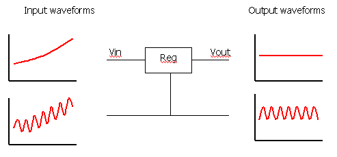
The response time of the voltage regulator means that if we inject a high frequency AC voltage on top of the DC voltage at the input of the voltage regulator, rather than responding to the increases and decreases of the input voltage, the regulator will simply let the AC voltage through:
The motors and speed controller in a robot are the largest generators of electrical noise. The noise produced will be at frequencies from near DC right up to several tens of megaHertz. Any noise at around the 40MHz radio frequency will cause the receiver to decode that in addition to the signal from the antenna (which is already at a very low signal strength). This is a very common cause of bad radio communications in fighting robots.
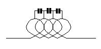
Some BEC circuits I have seen attempt to reduce the effect of high frequency noise by inserting a series inductor in the supply path to the regulator. This will have little effect unless you are either lucky or strict precautions are taken with the circuit layout and the inductor used. It is likely that a 40MHz noise signal will simply bypass the inductor due to the capacitance between each turn of the inductor coil:
Of course an inductor in the supply line does not solve any conducted interference or line-bounce problems.
So what can be done about it? The best solution of all is to disconnect the power circuitry which is generating all this noise from the receiver and electronics circuitry which is susceptible to the noise. That is, avoid battery eliminator circuits. That is a general rule of thumb which is virtually guaranteed to solve many of your comms problems. However, if you really insist on using just one battery in your robot, there are alternatives.
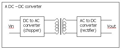
DC to DC converters are similar to voltage regulators, but differ in one great respect - isolation. When converting AC voltages, a transformer is used. Transformers are electrically isolated from one side to the other. This is because the input energy is converted to magnetic energy, and then back to electrical energy again at the output. A DC-DC converter first converts the input DC voltage to AC, then shifts the voltage of this using a transformer. Finally, the transformer's AC output voltage is rectified back to a DC voltage. The ground terminal on the input side is not electrically connected to the ground terminal on the output side.
Using a DC-DC converter may solve some of your problems, but the circuits inside them still have response times, and any high frequency noise on the input may well be transmitted through to the output side. Given this, I cannot recommend using them.
The best and simplest solution is to use two separate batteries. One often-quoted disadvantage of this method is that the receiver battery may become discharged and forgotten about. Well that is part of the responsibility of being in a fighting robot team - to have a written checklist of things that are required to do between bouts. Removing the receiver battery to recharge it may be difficult. In this case, it is quite easy to have a removeable link that can recharge the receiver battery from the main battery. This link could even be integrated into the main power removeable link that is required under most fighting robot league's rules. An example circuit is shown below.
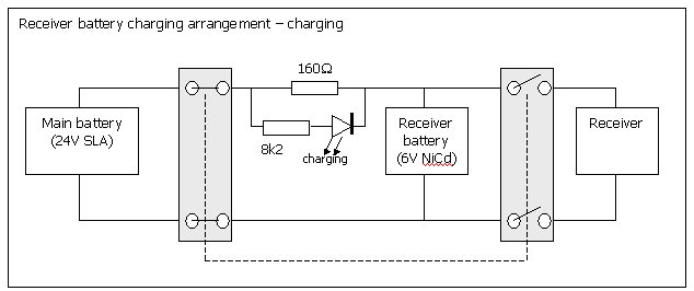
In this configuration, the left hand switch is closed and the right hand one is open (they are both part of the same QPDT switch). The NiCd is charged through the 160Ω resistor, and the receiver itself is disconnected. The resistor value should be chosen to supply about 110mA to the NiCd. It's value should be the main battery voltage minus the NiCd voltage divided by 110mA. The voltage drop across this resistor is used to light the 'Charging' LED. When the battery is fully charged, the switch is thrown the other way:
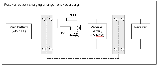
In this configuration, the main battery is completely disconnected, and the receiver battery powers the receiver. Since there is no current passing through the 160Ω resistor, the LED is not lit.
http://www20.brinkster.com/antweights/5%20Volt%20Regulator.html
http://www.teambigbro.co.uk/regulator.html
Or you can buy one::
http://www.technobots.co.uk/en-gb/dept_408.html
http://www.robotcombat.com/marketplace_elect_other.html