
As the equation in the inductors section (repeated here) shows
the voltage generated will be greater as the inductance increases, the current increases, or the time to switch decreases.
A DC motor consists of a commutator, which is continually, and quickly switching high currents into a highly inductive load. It is no surprise therefore that sparking can occur at the commutator.
A wire with 200 volts on it (relative to the earth potential) is situated 2 metres above the ground. This creates an electric field between the wire and the ground directly below it of 200/2 = 100 Volts per metre. This electric field cannot be measured with a voltmeter since placing the voltmeter and its leads in the space will affect the field. However, an electroscope can be used, and if this was placed half way between the wire and the ground, it would show a voltage of 100V, and if it was 50cm from the ground, it would show 50V. The circuit board shown in the diagram will be at a potential of 100V relative to ground. The electric field is linear as shown with the dotted lines in the diagram above. Every point on the earth is at the same potential (0v) becuase the earth is conductive, and so if there were any imbalance, current would flow in the earth until the imbalance was rectified.
If there are any metal objects in the area, every point on the metal object would be at the same potential too. Now imagine a metal box is introduced into the space between the wire and earth:

The metal box is 1 metre high, and is placed in the centre between the wire and ground. Now we know that the top of the box must be at the same potential as the bottom of the box. The total air gap is now only 1 metre, but there is still 200 Volts between the wire and earth. Therefore the electric field strength in the air above and below the box must now be 200 / 1 = 200 Volts per metre. The box must be at 200 V/m x 50cm = 100V potential. The areas to the left and right of the box will have varying field strengths, until at quite distance away fom the box the field strength will again be 100V/m as in the case before the box was placed there. Iso-potential lines can be drawn showing areas of the same potential:
Now lets put a circuit board inside the box. The top of the box is at 100V relative to ground, and so is the bottom of the box, so anything inside the box will have a potential of 100V relative to ground on it too.
Now lets get a bot more realistic. say the wire had 200V a.c. on it (this can represent a noisy, spikey motor supply wire for example). Then the metal box will have 100 Volts a.c. on it. Anything inside the box will have the same 100V a.c. potential on it..
Now lets put a circuit board inside the box, with a circuit which references to 0v, and then ground the box with a wire:
The whole wire must be at the same potential (thats what wires do!), and it is connected to the box, so the box must be at ground potential , 0V. The top of the box, and anything inside it must be at ground potential. The electric field strength in the air above the box is now 200V / 50cm = 400 V/m, but that has no effect on anything inside the box. The contents of the box are entirely insulated from any electric fields outside the box. This is called a Faraday Cage.
In a robot, of course you cant connect the box to earth! However, it only needs to be connected to a point of constant potential with respect to the circuit. The battery negative is a good choice. It is likely that the robot fram will also be connected to battery negative.
The box can be made of any electrcally conductive material (the lower resistance the better to ensure that the whole box is at the same potential). However, as we shall see later, it is best to make it a ferromagnetic material like iron or steel.
where l is the length of the maximum dimension of the hole, in metres. A rule of thumb that can be used is that the hole mustnt be bigger than a tenth of the wavelength. The wavelength is related to the frequency by the equation

C, the speed of light, is about 300 million meters per second in air, so at the radio control frequency of 40MHz, the holes must be smaller than 75cm. This should be easy enough! For 459MHz, the size is 6.5cm.
For electric fields, the shielding can be any conducting material (e.g. steel, aluminium, copper). Although any conducting material will reduce magnetic fields (since the field generates eddy currents in the material which generate a magnetic field in the opposite direction to the primary field), magnetic materials are better. Soft iron is best, but steel is more practical to use.
Remember that the shield MUST BE EARTHED to be effective! And the earthing should be at ONE POINT ONLY (see below).
There is also a reflection effect based on Lens' law. When a metal plate is in an alternating magnetic field, eddy currents perpendicular to the magnetic field are induced in the plate:
The eddy currents themselves generate a magnetic field in the opposing direction to the incident field, thereby partially cancelling it out. This is the same pronciple that generates a back emf in electric motors.

This shows a battery supplying current to a motor, and to some electronic circuitry. When the motor is running, it takes a current im, from the battery. When it is not running, or there is no load on it, it takes little or no current.
The ground line and the battery supply line have a small resistance, Rsand Rg. When the current flows, these drop a voltage imRs and imRg, which causes the voltage at the electronic circuitry to drop from Vbatt by a voltage im(Rs+ Rg). The switching of the current on and off by the motor commutator will mean that the voltage supply to the electronic circuitry has a lot of noise on it, which can cause the electronics to malfunction.
Here is an alternative circuit using star gounding:

Even with start grounding, there is still a little common wiring inside the battery itself. All batteries have an internal resistance, and this resistance is, of course, in both the motor and electronics paths.
There may be resistance in the wires from the battery to the electronics, but since the electronics will not be drawing any appreciable current, the voltage drop across that resistance will be negligable.
A more suitable system altogether is to isolate the electronics and motors altogether, using a separate battery for the electronics:

An alternative form of this is to use a DC-DC converter. This generates an isolated DC supply from the existing supply. However, the converter output tracks the input so lowish frequency fluctuation son the input voltage may be transferred through to the output. However, it is better than no isolation.
Of course it is highly likely that the electronics will eventually be driving the motor, via PWM generators, speed controllers, etc. If an electrical signal were sent from the electronics circuit to the motor circuit, it would have to be referred to ground. A voltage cannot exist in itself, it is a potential difference between two points. Therefore, if a signal connection exists between the two circuits of Figure 3, their grounds (or V+) must be connected together also. This sets up another ground loop, whch we dont want.
We need a means of controlling the right hand side circuit of figure 3 from the left hand side circuit, without an electrical connection. This is accomplished using light (which doesnt need a reference ground!) in the form of optoisolators:
The RC network has several effects:
Capacitors will restrict an instantaneous change in voltage. A capacitor, therefore, is useful to counter the destructive voltages generated across the MOSFET. When the MOSFET is on, the capacitor is out of the circuit (it is shorted out). As the MOSFET is turned off any change in voltage is restricted by the capacitor.
A capacitor alone is not an ideal solution. When the MOSFET is off, the capacitor charges up to the battery voltage. As the MOSFET turns on, an inrush of current results as the capacitor discharges, limited only by a MOSFET on-resistance and capacitor series resistance, and damage may still result. For this reason, a resistor is configured in series with the capacitor. The higher the resistance value, the smaller the inrush current but the less effective is the capacitor.
An Acrobat document describing the design of snubber networks is available here, although this is rather technical. Snubbers can be bought off-the-shelf from general electronic suppliers. Some manufacturers of snubbers are listed in the links section at the bottom of this page.
For more details on snubber network design, there is a new page devoted to the subject here.
In a car, the alternator is suppressed with a large capacitor across its terminals, to stop noise being picked up by the car radio. We must do exactly the same with our motors.
Large capacitors, like electrolytic types, tend to have a large inductance. This means that although they block DC signals, they also block high frequency noise. To circumvent this, a smaller ceramic capacitor can be placed in parallel with it:
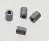
To help dampen high frequency noise, inductance can be added in series too. Finding inductors that can pass the sort of currents our motors take is difficult, so ferrite beads can be used. These are strung onto the motor supply wires. They do not give rise to a very high inductance but every little helps.
It may not only be the main drive motors that require suppression. Any device in the robot which is switching current may require similar suppression across its supply terminals. Signal wires between devices in the robot may benefit from ferrite beads, and/or capacitor suppression (as long as they are not intended to carry high frequencies do not suppress the signal from the antenna to the receiver!).
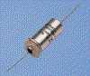
A better type of small capacitor to use for low-current suppression is the feed-through type. This does not suffer nearly so much from inductance, and so can suppress to higher frequencies. The graph in the figure shows curves for the attenuation of the two types of capacitor. The normal type is the black line and the feed-through type is the red line:

Other suppression components are also available, like three terminal PI-network filters. These have two capacitors and an inductor to filter high frequency noise:

Many others are available, have a look at this Murata document for details.
Special filters are also available for DC motor suppression, although these are rather expensive:

The capacitors should actually be placed from each motor terminal to ground. This provides a low impedance path for high frequency noise straight to ground, rather than back into our circuits:
The often quoted values of 10nF - 100nF ceramics are suitable.
EMC articles
Chipcenter EMC archive
Solving Motor Failures Due to High Peak Voltages and Fast Rise Times
Evaluation of Soft Switching for electric vehicle (EV) and HEV Motor Drives
Technobots - "EMI and how to deal with it" by Tim Mann
Controlling voltage spikes (motor suppression). ST Acrobat document.
http://us.st.com/stonline/books/pdf/docs/1703.pdf
Reducing EMC problems with digital logic controlling inductive loads.
http://chipcenter.com/eexpert/bkimmel/archive.html
Murata
Toko
LCR Components
Tusonix
Oxley Components
Epcos (Siemens)
MTE Corp
MTE Corp
EFC
ECI
Commonwealth Sprague