V1.02 17-Jun-04
I cannot guarantee any of the circuits linked to will work as advertised, and I haven't built any of them myself.
I will go through these in turn, describe the possibilities, approximate cost, and usefulness.
Many of these items of test equipment are quite expensive to buy new. While electronics companies are constantly upgrading their test equipment, this means that old test equipment is constantly finding its way onto the second hand market. The easiest place to find this stuff is on the eBay or the Loot web sites.
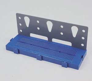
OK, so why is this section headed "Breadboard". Because this is the second best way to prototype your circuits. It consists of a large array of holes, which are organised into strips of six or so which are electrically connected together underneath:
It's well worth buying a bag of solid core wire links to use on these boards as well since it's a very tedious business making your own. That's up to you.
Why did I say that this is the second best method? Because the best method, ratsnesting, is a bit expensive for hobbyists since you only use the components once. This method involves flattening all ICs legs out, and soldering all the components together so they sit in roughly the same pattern as the circuit diagram. This is sometimes a bit difficult around ICs since circuit diagrams don't usually draw the boxes of ICs with their pin numbers in their physical locations, but generally in logical positions. However, all resistors, capacitors, transistors, and power rails can be positioned this way. This method makes it very easy to check the circuit out with a meter or oscilloscope, since everything is in its logical position, and reference to the circuit diagram is easy. The resistors and some capacitors may be used in the final circuit on PCB, but the ICs are generally only good for scrap after this treatment!
[E2] Electronics prototyping links
http://www.epanorama.net/links/basics.html#prototype
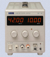
You don't want to build a power supply circuit for every circuit that you want to test, and batteries don't come in the range 4.75 - 5.25v (TTL power supply voltage range), so a samlle bench power supply is invaluable. It should have outputs for +5v for logic, and a larger bipolar range for opamp circuits, say +/-12v or +/-15v. If you want high currents at 12v, then a car battery is probably the cheapest source.
Bench power supplies are very expensive to buy from electronics distributors such as Maplin (starting around £120), so it may be a good idea to make your own. Some links for circuits and projects are shown below:
Some power supply circuits/projects
http://www.epanorama.net/documents/components/lm317.html
http://www.aaroncake.net/circuits/supply.htm
http://ourworld.compuserve.com/homepages/Bill_Bowden/page12.htm
http://www.mitedu.freeserve.co.uk/Circuits/Power/l200var.html
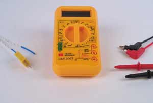
DMMs are so cheap now that there is no reason not to have one. Maplin supply a range of DMMs that start frm £17 - don't bother buying expensive stuff like Fluke meters, these are perfectly usable.
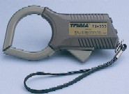
A very useful tool to go with the DMM is a clamp current meter. This will allow you to measure the very large currents coming from the battery to the speed controllers and motors. CPC supply one (order code IN00710) made by Tenma (model number 72-6174) for £30.
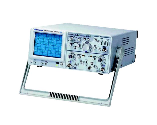
An oscilloscope, if you can afford one, is the most useful piece of test equipment of all. It gives you information in the extra dimension of time. If you have never used one, have a look at this page which describes what they do. Basically, they draw a graoh of voltage aginst time for the signal you are viewing.
There are two different types, Analogue scopes, and Digital Storage Oscilloscopes (DSOs). Unfortunately, both are very expensive to buy new (the cheapest analogue scope will cost around £250), and DSOs are expecially expensive.
You may have seen "PC based" scopes advertised such as the PicoTech scope which plugs into the PC printer port. The reasonably priced version of this only has one channel. One major advantage of oscilloscopes generally is that you can see how one signal is affected by another, for example, the input and output of a section of the circuit. Not being able to see the two side by side is a large disadvantage, and I can't recommend buying a single channel oscilloscope of any variety.
There are projects to build PC-based oscilloscopes available. One well described one is presented here, and another is here.
The best bet if you want to buy an oscilloscope is to get hold of a second hand one. Have a look on eBay or the Loot. You should be able to pick up a good quality dual channel analogue scope for well under £100.
If your PC has a sound card, then it has all the hardware required to make a DSO that can sample up to 50kHz or so. Since the analogue input on a sound card is stereo, a dual trace scope can be made. This article dexcribes how. Of course the input voltage range is limited, and any voltage which exceeded this could possibly damage your sound card or whole PC so be careful!
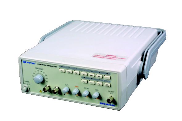
Often you will want to generate a signal to test a circuit that you have built. Most signal generators will generate square waves, sine waves, and triangular waves over a wide frequency range. These are generally called "Function Generators". A full signal generator may add to this the ability to modulate the signals (for example to generate AM or FM modulated signals), and to vary the square wave mark-space ratio. Some may even generate more complex logic signals.
A basic square wave generator is a useful addition to the hobbyists bench. Complex logic signal syntheis is also. This can be used for example to generate a radio control PPM servo signal (20ms off, then 1ms-2ms on).
Maplin supply a kit signal generator that connects to a PC, and allows arbitrary waveforms to be generated. I have not used this so cannot gove any comment on it but it seems to be useful and reasonably priced.
There are a few circuits for performing this function available on the web.
Here are some:
http://www.repairfaq.org/filipg/RC/F_Servos.html
http://www.tuug.utu.fi/~isaarine/electronics/servo-test-1/
http://www.electric-flight.org.uk/data/servo-driver.htm
http://www.electronic-engineering.ch/radiocontrol/circuits/servo-check/checker-fut.html
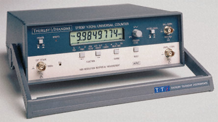
A good frequency counter should be able to measure frequency, period, mark-space
ratio, and delays. It should have two channels to perform comparitive
measurements between two signals. They are generally cheaper instruments than
frequency generators or oscilloscopes. Maplin supply a couple new, or there are
a few projects to build one on the web, including:
http://webook.fset.de/20091999PHCHO/RU3AEP/Digital%20frequency%20counter%20by%20Valentin%20Gvozdev.htm
http://www.sadars.org.uk/counter1.html
http://www.hanssummers.com/electronics/equipment/radiofreqcounter/intro.htm
http://www.hanssummers.com/electronics/equipment/counter/intro.htm
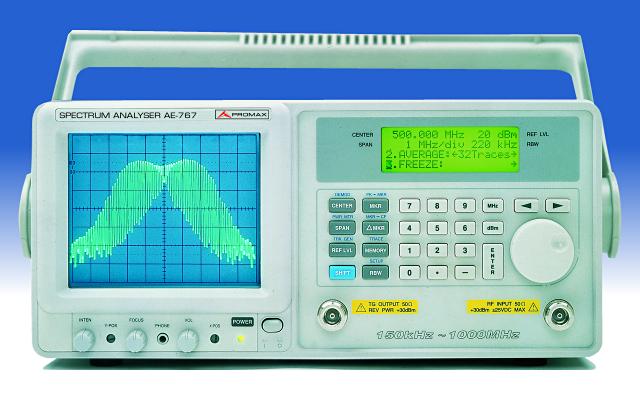
If you are going to be playing about with radio transmitters and receivers, a spectrum analyser really is a useful product. Whereas an oscilloscope draws a graph of a signal with time on the X axis, a spectrum analyser does the same with frequency on the X axis. It will show exactly the frequencies and signal strengths at those frequencies that are present.
The down side is that these are incredibly expensive instruments! Those cheap spectrum analysers that you see for sale cover only the audio range, up 20kHz at most For our radio use, we need to cover the 40MHz band, and preferably up to 80, 120 or even 160MHz just to see if we are generating any "harmonic" signals at higher frequencies.
An example of the Tektronix spectrum analyser is shown here, along with the price of $25,000! You may be able to get a very old second hand one for something resembling a reasonable price, but probably not!
If you are designing your own antenna for your robot, you would really want one of these. They will tell you the impedance of your antenna, and the resonant frequency. We would want these to be 50 Ohms and 40MHz respectively. However, just placing the whip antenna near a metallic surface will change both these quantities, and chopping a few inches off will drastically change it. If you are going to design uyour own antenna, or play about with it, renting one of these for a couple of days might be worthwhile.
An example of one can be found here, costing £330.