
1. Introduction
Spinning disks can be the most destructive of weapons. The amount of damage caused to an opponent is determined in part by how much energy you can impart into the opponent. The more energy in each strike, the greater the damage will be. A single strike weapon which starts off stationary, and then is moved to strike the opponent can only gain energy in the time between it starting to move and striking the opponent. A spinning disc however can have energy transferred into it over a longer period of time until the strike.
Energy is measured in Joules. It is a measure of power over a given amount of time. In electrical terms, power is voltage × current, so electrical energy is voltage × current × time:
P = vi
E = vit
Energy can neither be created or destroyed (we’ll ignore E=mc2 here!), it can only be transformed from one type to another. All types of energy are measured in Joules. There are many types, and many equations governing each type, most of which are quite simple. Potential Energy is the energy stored in a body which has been raised to a height against gravity, or stretched into a spring – it can potentially be used at any time. Kinetic Energy is energy stored in a body because it is moving. It may be moving in a straight line or spinning in a circular motion (or any other motion for that matter). Heat Energy is energy stored in a body because it is hot. There are many other forms, for example chemical, biochemical, sound, radiation, etc, but these are not important in this discussion.
2. The physics of spinning disks
There are basic laws of physics which govern moving objects, formulated by Newton in his three laws of motion (see http://csep10.phys.utk.edu/astr161/lect/history/newton3laws.html ). These may well be familiar to you in their normal form. The equations we are interested in are:
Force = mass × acceleration (Newton’s 2nd law)
F = ma
Power = force × velocity
P = Fv
Kinetic energy = ½ × mass × velocity squared
E = ½mv2
These equations work for bodies moving in straight lines. If they are moving in a circular motion like a spinning disc, we must replace the variables in the equations with versions for circular motion, according to the following table:
|
Linear motion |
Rotational motion |
||
|
Linear Quantity |
Quantity |
Symbol |
Units |
|
Force |
Torque |
T |
Nm |
|
Distance |
Angle |
θ |
radians (rad) |
|
Mass |
Moment Of Inertia |
I |
kgm2 |
|
Velocity |
Angular Velocity |
ω |
rad/s |
|
Acceleration |
Angular Acceleration |
α |
rad/s2 |
Therefore the three equations above now become:
torque = moment of inertia × angular acceleration
T = Iα
Power = torque × angular velocity
P = TΩ
Kinetic energy = ½ × moment of inertia × angular velocity squared
E = ½IΩ2
2.1. Radians
Notice in the units column the units for angle is radians, not degrees. The reason for this is quite complex, but suffice to say you must use radians if you want the equations to work. What is a radian? Well, there are 2π of them in a full circle, so

2.2. Moment of inertia
The moment of inertia (MOI) is the equivalent of mass in linear movement. However, you can’t just weigh your object to find out what it is because it depends not only on the mass, but on how the mass is distributed in the shape of the object.
Simple shapes have simple equations to calculate the moment of inertia. More complicated shapes must be broken down into simpler shapes, then all the MOIs added up to find the total MOI. The linear equivalent of this is that the mass of a complicated shape can be found by breaking the shape up into simpler shapes and adding up the individual masses.
The equations of MOI for some simple shapes are:
|
Object and rotational centre |
Picture |
Equation |
|
Cylinder rotating about its axis |
a |
½mr2 |
|
Ring rotating about its centre point (bicycle wheel) |
b |
½πρh(ro4-ri4) |
|
Spoke rotating about its endpoint |
c |
1 /3 ml2 |
where:
m = mass (kg)
r = radius (m)
ρ = density (kg/m3)
ro = outer radius of ring (m)
ri = inner radius of ring (m)
l = length of spoke
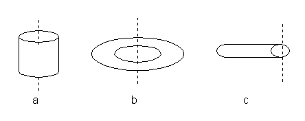
Other MOIs can be found in the table here. If you are interested, and have a mathematical mind, the proofs of these equations are presented here.
Let’s take an example and calculate the MOI.
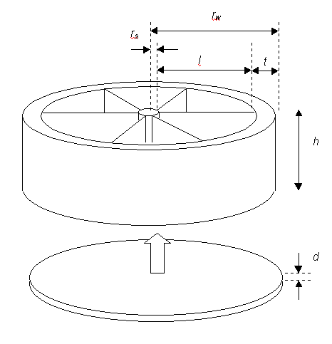
This shape is like a cartwheel. It has a solid outer rim, a solid shaft, and six spokes. It then has a solid disk stuck on the bottom, and another on top (not shown in diagram). This shape would make a reasonable spinning disk. We’ll assume the spokes have a thickness ts, which is very thin.
First we must break the design into simple parts that we know the equation of MOI for. These are shown in the table below. In this table we also calculate the mass for each part, which is its volume multiplied by its density, ρ.
|
Part |
Standard eqn |
Specific eqn |
Mass |
Qty |
|
Central shaft |
½mr2 |
½mrs2 |
πrs2hρ |
1 |
|
Outer ring |
½πρh(ro4-ri4) |
½πρh(rw4-(rw-t)4) |
ρπh(rw2-[rw-t] 2) |
1 |
|
Spokes |
1 /3ml2 |
1 /3ml2 |
hltsρ |
6 |
|
Disks |
½mr2 |
½mrw2 |
πrw2dρ |
2 |
Let’s try some real numbers in this. We’ll use the following dimensions:
rw = 20cm = 0.2mWe’ll also assume the material is steel so the density, ρ, is 7800 kg/m3 for all parts. First work out the mass of a single item of each part:
|
Part |
mass eqn |
mass (kg) |
|
Central shaft |
πrs2hρ |
0.3 |
|
Outer ring |
ρπh(rw2-[rw-t] 2) |
5.6 |
|
Spokes |
hltsρ |
0.3 |
|
Disks |
πrw2dρ |
0.98 |
Now we can work out the MOI for each part, and add them up to get the total:
|
Part |
Specific eqn |
mass (kg) |
MOI |
quantity |
Total MOI |
|
Central shaft |
½mrs2 |
0.3 |
0.000059 |
1 |
0.000059 |
|
Outer ring |
½πρh(rw4-(rw-t)4) |
5.6 |
0.202 |
1 |
0.202 |
|
Spokes |
1 /3ml2 |
0.3 |
0.005 |
6 |
0.03 |
|
Disks |
½mrw2 |
0.98 |
0.0196 |
2 |
0.0392 |
|
Total |
0.271 |
Note that even though the central shaft has a reasonable mass, its MOI is tiny. This is because it is located right at the centre of the disk. The MOI is proportional to the radius squared. Therefore when designing your disk, you should place the weight distribution as far out as possible. This also means that increasing the radius of your disc has a far greater effect than increasing the mass of it.
Note that we have ignored the MOI of the motor itself. This is a fairly safe approximation since the motor parts are very near the rotational axis (motors are built that way) so its MOI will be relatively small. Some motor manufacturers may quote it in their literature, but it should be negligable in comparison to your disk.
2.3. Kinetic energy of the disk
Now we know the MOI, the kinetic energy is easy to calculate. Let’s assume the disc is spinning at 4000rpm. First we must convert this to speed in radians per second. We can use the following conversion table:
|
To convert |
into |
multiply by |
|
rpm |
rad/s |
0.105 |
|
rad/s |
rpm |
9.55 |
So the angular speed is 419 rad/s. The kinetic energy is given by the equation:
E = ½IΩ2 = 0.5 × 0.271 × 4192 = 23800 J.
Let’s put this amount of energy in perspective. The potential energy due to gravity is given by the equation:
E = mgh
where m is the mass, g is acceleration due to gravity (=9.81 m/s2 at the surface of the earth) and h is the height lifted to. How high could this amount of energy cause an opponent robot of 100kg mass to fly into the air?
h = E/mg = 24 metres!
That’s a lot of energy! Of course the spinning disk would need to spin vertically and would need to get right under the opponent, which isn’t very practical, but you can get the idea of how much energy this is.
Notice that the kinetic energy is proportional to the angular velocity squared. That means doubling the speed of the disc will quadruple the energy. Therefore gearing the motor to drive the disk faster will also be an advantage, although it will take longer to get up to speed.
To get some idea of a target energy, the disk of Hypnodisk, the finalist in series 4 of the Robot Wars competition, had an energy of approximately 6kJ.
2.4. Getting the energy from the battery
If a motor is used to spin the disk, then that 23800J must come from the battery. How much will this take out of the battery? Well, the capacity of the battery is measured in Ampere-hours (see the battery section for details). The voltage of the battery is fixed, so the energy in the battery is:
E = vit = Ah × 3600 × v
The 3600 is to convert Ampere hours into Ampere seconds. For a 12 volt 20Ah battery, the energy is 864kJ. Therefore every spin-up of the disk is going to take 2.7% of the battery capacity, at least (see the battery section for how the capacity derates for various reasons).
2.5. Time to spin-up
"How long will it take for an DC electric motor to spin the disk up to speed?"
This is an important question, and is very complicated to answer. When a motor drives a load from start, it accelerates in a negative exponential fashion, like the graph below:
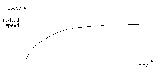
The actual speed will never reach the no-load speed, but will get closer and closer as time goes on. Therefore we can’t specify a time when it reaches the no-load speed. Instead, we quote a time taken to get to a certain proportion of the target speed, 63% in fact. (This percentage may seem strange, but it has a complex mathematical reason which I won’t go into). This time is called the time constant, and is given the symbol ‘τ‘. In electronic circuits with a capacitor being charged through a resistor, the time constant is τ = RC, and this is how long it takes for the voltage on the capacitor to reach 63% of the charging voltage. This behaviour is common in lots of cases in nature.
OK, so let’s rephrase the question, "How long will it take for an electric DC motor to spin the disk up to 63% of the target speed?"
I won’t present the workings of this because they are very mathematical. If you are interested, they are here. The final equation, though, is:
For permanent magnet motors: t = Ω1/T1× I
For series wound motors: t = 0.931 × Ω1/T1 × I
Where Ω1 is the no-load speed of the motor in radians per second, and T1 is the stall torque of the motor in Newton-metres. Both these values can be obtained from the motor characteristic graph, see the motors section for details.
2.6. Power rating of the motor
We have seen in the previous sections that we can select the motor we want to use based on the energy requirement of the disk, and the maximum required time to spin up to speed. However, the motor requirements are in terms of stall torque and no-load speed. These parameters are often not known if the motor has come from dubious sources like a scrap-yard! However, sometimes we do know the approximate power rating of the motor. How does this power rating relate to the stall torque and no-load speed?
For a permanent magnet motor, the torque-speed graph looks like this:

The power of the motor at any point on the graph is Torque × speed. We can add the power curve to the graph:


This operating point is approximately where the speed has dropped off 25% from no-load speed. Therefore the power at this point is:
P = ¼T1 × ¾ Ω1 = 3/16T1 Ω1
This is only an approximation. The maximum power that a motor can handle is determined greatly by its mechanical design – how well it can dissipate the heat generated into the surrounding air.
Motors may have two different power ratings, one for continuous use (referred to as S1), and one for intermittent use (referred to as S2). For example, the Lynch 12V motor has ratings:
|
rating |
time / condition |
power |
|
S1 |
continuous |
1.2kW |
|
continuous with external blower |
2.4kW |
|
|
S2 |
1 minute |
3kW |
|
5 seconds |
4.2kW |
So, how can we determine the power rating of motor that we require? Remember from the first equations in this page that energy is power × time. Therefore,
P = E ÷ t
We have already decided the maximum time we will allow for the disk to spin up to speed, and how much energy we want the disk to have. Therefore we can work out the average power during the spin-up process.
Example
Let’s take an example using the Bosch GPA750 permanent magnet DC motor. This motor has a nominal power rating (continuous) of 750W, a stall torque of 11Nm, and a no-load speed of 4000rpm = 419 rad/s. Let’s assume we have a disk with MOI = 0.2 kgm2.
The energy of the disc will be
E = ½IΩ2 = 0.5 × 0.2 × 4192 = 17.6 kJ.
The spin-up time (to 63% no-load speed) is
t = Ω1 /T1 × I = 419/11 × 0.2 = 7.6 seconds.
The average power taken to spin this disc up to speed is then…
P = E ÷ t = 17.6kJ ÷ 7.6s = 2.3kW
Note that this is a lot larger than the power rating of the GPA750 motor, but it is only operating over a time period of 7.6 seconds (plus a little more to get from 63% final speed to approximately the final speed). The table of power ratings for the Lynch motor above show that the short-term (5s in that case) power rating may be 3 or 4 times that of the continuous power rating.
What is the instantaneous power of the motor as the disk spins up?
As the disk spins up to speed, the speed increases negative-exponentially (as we have seen in the graph previously), and the torque reduces in the same manner. Now power = torque × speed, so the instantaneous power curve is rather complicated.
The speed increases according to the equation
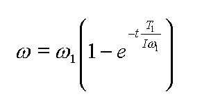
And the torque is a function of the speed:
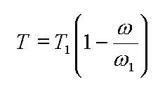
Then the instantaneous power is the torque × speed
P = TΩ

The average power is the area under the Power curve in the graph above, and is given by the rather complicated equation:
P = T1/ts × (1/Ω1 – 1) × (e^[-tsT1/IΩ1] – 1)
where ts is the time interval over which the averaging is taken.
There is an Excel97 spreadsheet here in which you can enter the dimensions of your disk, and characteristics of your motor, and it will calculate the MOI (based on any complex shape you enter), mass of the disk, energy, spin-up time, and it will also draw the spin-up curves. Take a look, it may save you a lot of time when designing your disk! Note that there are no macros in this spreadsheet so no viruses to worry about.
2.7. Gearing
Adding gearing between the motor and the disk will affect the final speed of the disc and the time to spin up. The amount of gearing is measured by the gearing ratio, G:
G = output speed ÷ input speed
The gearing also has the effect of decreasing the output torque though:
output torque = input torque ÷ G
This follows from the fact that the power coming out of the gearbox must be the same as the power that went in (neglecting heat loss), and power is the product of speed and torque:
Power = input torque × input speed = output torque × output speed
If a gear ratio of 2 is implemented, then a motor with no-load speed 2500rpm will spin the disc at 5000rpm. This will quadruple the energy stored in the disc as we have seen previously. The energy is proportional to the square of the gear ratio:
E ∝ G2
What happens to the spin-up time? We know that the speed will be increased by G and the torque will be decreased by G:
output speed = input speed × G
output torque = input torque ÷ G
This means that our effective stall torque and no-load speeds are now different, such that:
ωg = Ω1 × G
Tg = T1 ÷ G
Therefore, the spin-up time equation is now:
t = Ωg/Tg × I = (Ω1 × G) ÷ (T1 ÷ G) × I
t = IG2Ω1/T1
So the spin up time has increased by the gearing ratio squared. We could have predicted this though. This is the big disadvantage with gearing.
Depending on how the gearing is implemented, the gearing ratio is easily calculated. The following table gives equations for the gearing ratio for various types of gear.
|
Method of gearing |
Gear ratio |
|
Friction drive. Motor shaft drives a tyred-wheel pressed against the disk shaft. |
G = Rmw ÷ Rds Cmw = Motor wheel radiusCds = Disk shaft radius |
|
Toothed belt, sprocket & chain, or two meshed gear wheels. |
G = nm ÷ nd nm = Number of teeth on motor wheelnd = Number of teeth on disk wheel |
|
Worm and wheel (only for gearing down) |
G = p ÷ (2πR) p = Pitch of worm threadR = Radius of gear wheel |
2.8. The gyroscopic effect.
The gyroscopic effect causes a rotating body to exert a force perpendicular to the force acted upon it. The best description of the gyroscopic effect I could find is at http://www.howstuffworks.com/gyroscope.htm.
If your disk is mounted horizontally, the gyroscopic effect will not be of too much concern to you, and can even be an advantage. For example, if your disk is rotating clockwise as seen from above, and an opponent tries to lift the front of your robot in the air, the gyroscopic effect will resist this, but the resultant force will tend to tip your robot over to its left. If you are well stabilised side to side so you don’t get tipped over, this could be very disconcerting for the opponent driver!
If your spinning disk is mounted vertically, however, there may be a problem when you try to steer. If the disk is spinning on an axis from side to side of your robot, and when viewed from the left hand side is spinning clockwise (so the disk edge is going upwards at the front), then when you steer to the right, there will be a force tending to tip you over onto your right hand side, and when you steer left there will be a force tipping you over to the left. The greater the speed and moment of inertia of the disk, the greater this force will be, so it must be calculated into your robot design.
How can you counter this problem? One solution is to run two disks of equal moments of inertia and speeds, and on the same axle, in opposite directions to each other. The gyroscopic force of one will then cancel the force from the other. However, this may reduce the effectiveness of your disk.
3. Materials for the disk.
The disk needs to be quite sturdy if it is to survive the impacts that are intended to destroy the opposition. Therefore a tough material such as steel or titanium is ideal for the outer rim. If there are to be any blades fixed to the outer rim, these must be made from even tougher material. Hardened metals are not suitable for the blades, since these will be impacting, and hardened metals are more brittle than their annealed forms.
Titanium may be an unnecessary expense since the disk must also have a reasonable mass to get the required moment of inertia. Using steel will allow the spin speed to be reduced for the same energy requirement as titanium. However, a light-rimmed disk may be required to keep the robot inside the weight limit for its class. In this case, the spin speed may need increasing using gearing to attain the energy requirement.
For a table of materials and their properties, see the section on materials.
4. Mounting & bearings
Whether the disk is mounted horizontally or vertically, it is unlikely that the motor shaft and bearings will be able to support the disk, especially during impacts. Therefore it will need to be supported by other means and the drive from the motor should not be load-bearing.
Some examples are shown below:
Example 1. Horizontally disk, direct connetion.
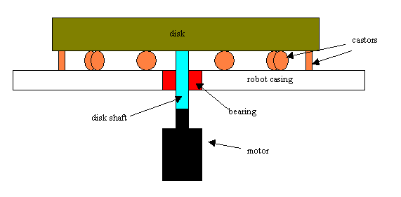
The weight of the disk is supported on castors around the periphery of the disk, and the shaft has its own bearing through the casing of the robot. The motor shaft is directly connected to the shaft inside the robot with no gearing. The joint between the motor and disk shaft should allow some flexibilty – e.g. and Oldham coupling or universal joint.
Example 2. Horizontal disk with friction gearing.
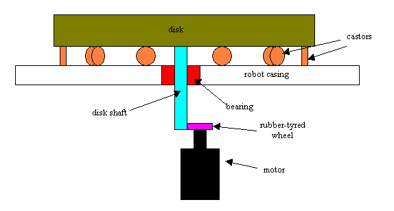
Again the weight of the disk is supported on castors. However, the motor drives a rubber-tyred wheel which is pressed against the shaft of the disk. This allows gearing, and implements some clutch action to prevent the motor stalling when the disk stalls (a stalled motor pulls a large current, and if stalled for some time may burn out).
Example 3. Vertical disk with sprocket & chain drive.
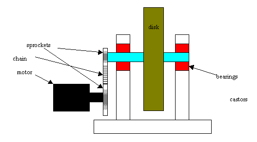
The disk axle has a bearing at each end. The shaft extends through one of the bearings and a sprocket is mounted on the end of the axle. This sprocket is driven by a chain from another sprocket mounted on the motor shaft.
Bearings.
Arthur Chilcott, a regular on the Robot Wars Forum and member of the Mortis team has the following advice: "Regarding the use of bearings in spinners is, don't use ball races, they are not designed to cope with shock loads. The best type of bearing for shock loading is a plain bush, for example, Glacier DU or Igus Iglidur, the Du is a steel shell with sintered bronze facing, impregnated with PTFE, the Iglidur is a reinforced plastic." Since I have no experience of bearings whatsoever, I won;t add anything to that!
One important consideration, especially if you are intending to have a high-speed disk, is the disk balance. If the disk is not well-balanced, or the bearings are a little loose, then the disk is likely to shake the robot to pieces in a short time. At best it will make control of the robot very difficult.
The balance of a perfect circular disk can be tested and rectified using the following method: Spin the disk at a speed such that it just starts to wobble. With a piece of chalk approach the edge of the disk until the disk just brushes the chalk only when the wobble causes that part of the disk to do so. This indicates the part of the disk which is slightly too heavy. Now sellotape a coin on the opposite side, and retest. If there is still a wobble on the same side, either move the coin outwards towards the edge, or use a heavier coin.
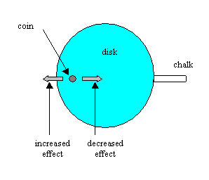
By adjusting the coin position like this you should be able to attain perfect balance. Once this is done, simply fix the coin down in the same place (on the underside if you don't want it visible!) using an epoxy resin such as Araldite.
5. Links
Moments of inertia
MOI
Gyroscopic effect
http://www.howstuffworks.com/gyroscope.htm.
Basic machines – an excellent technical online booklet covering many aspects of mechanical engineering.
http://www.tpub.com/machines/
Gears – part of the above document.
http://www.tpub.com/machines/6.htm