Making Sense of Sense Resistors
1. Temperature Effects
by Dennis
Feucht
Some components are
relatively unimportant in their effect on overall circuit behavior. Sense
resistors are not one of them. It may only be a resistor, but it's a very
important resistor with subtleties that can impede design progress.
Temperature
Coefficient
Sense resistors are usually power resistors in that they
dissipate non-negligible amounts of power and are typically rated at 0.5 to 5 W.
At the same time, they must hold their resistance value, for it contributes
proportionally to the current measurement. Temperature coefficient (TC) of
resistance is consequently of high design importance. Using a clipped length of
copper wire will demonstrate this point. In a motor drive, the torque will fall
off as the motor operates due to the increasing resistance of the copper sense
resistor, as it heats. Wire made of alloys with low TCs are available for use
instead.
But sometimes a copper sense
resistor, whether as a discrete wire resistor or a circuit-board trace, can be
used to advantage. The TC of copper is fairly constant over a wide temperature
range, and its positive TC of about +0.4 %/°C can be used to
compensate for the characteristically negative TC (–2.2 mV/°C)
of a semiconductor junction elsewhere in the current control loop.
Actual Sense
Resistors
One simple approach to sense resistors is to make your own out
of a low TC conductive material. Manganin wire, an alloy of copper, manganese,
and nickel, has a low TC of within
15 ppm/°C from 0 to
80 °C. AWG # 18 manganin wire has a resistivity of
0.361 /m.
Smaller diameters are available and the wire can be bought by the roll. Cut the
wire to length for the desired resistance, tin the ends, and solder into the
board. A manganin resistor is shown in Figure 1 (left). By keeping the half-loop
area small, inductance is minimized. The one shown has a resistance of
25 m.
/m.
Smaller diameters are available and the wire can be bought by the roll. Cut the
wire to length for the desired resistance, tin the ends, and solder into the
board. A manganin resistor is shown in Figure 1 (left). By keeping the half-loop
area small, inductance is minimized. The one shown has a resistance of
25 m.
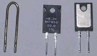
Figure 1: Homemade
and Commercial Sense Resistors
If you do not want to make
your own, the resistors shown on the right on Figure 1 (front and rear) are
commercially available power resistors made of a low-TC metal foil on an
anodized aluminum substrate, and in TO-220 or TO-247 packages. Several
companies, such as Caddock Electronics, now supply these accurate, low TC, power
resistors at an attractive price for power-circuit design.
Another
commonly-used low-TC material is nickel-chromium, or nichrome. Its
resistivity of 133  -cm requires less wire length than mangagin's 43 -cm, which can reduce
inductance for very low-value resistors. Manganin, however, is superior to
nichrome in TC and long-term stability of resistance value.
-cm requires less wire length than mangagin's 43 -cm, which can reduce
inductance for very low-value resistors. Manganin, however, is superior to
nichrome in TC and long-term stability of resistance value.
If future circuit-board
fabrication technology allows a wider range of substrate materials (more than
copper), thin-film power resistors can be integrated onto the board during
layout. With clever circuit design, even copper traces can be TC-compensated
with BJT junctions.
Kelvin Sensing
Resistors
Series parasitic resistance is also a nuisance for low-value
resistors. It is necessary to sense across the actual resistance of specified
value and not some of the component lead resistance in addition. To solve this
problem, 4-wire, or Kelvin, sensing is made possible with 4-wire
resistors, such as those shown on Figure 2. The leads are attached internally to
the desired resistance and are brought out of the package in pairs.
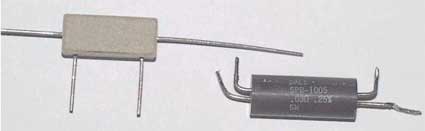
Figure 2: Kelvin Sensing Resistors
Kelvin-sensing resistors are also
available in foil-on-substrate form, as shown on Figure 3. (The quarter is for
size comparison.) The smaller, inner leads are 4-wire Kelvin sense leads while
the wider, outer leads are the drive leads.
Figure 3: Kelvin-sensing Resistors
in foil-on-substrate
form
Closure
Current-sense resistors for power electronics must be of low TC,
relatively high power rating, and accurate at low resistance values. Such
resistors are commercially available, in multiple packages, and at moderate
prices. If prices are too high for a given application, consider making instead
of buying sense resistors out of manganin wire, or for the lowest cost, use a
copper circuit-board trace compensated by a silicon junction.
2. Parasitic Series Inductance—Frequency Sweep Measurement
A sense resistor is not only
a resistor. A better model includes series inductance. The terminal leads (or
terminal traces for surface-mount resistors) contribute an inductive element. In
most resistor applications, this inductance is of no consequence, for it forms a
time constant that is very small. But when the resistance is also small, the
time constant, τ = L/R, becomes large enough so that the
frequency 1/τ lies too close to the loop bandwidth of the power circuit.
It is not difficult to encounter parasitic inductances in the 50 nH to 200 nH
range. This is too small a value to measure accurately on common RLC meters (or
"bridges"), but can be measured conveniently on the lab bench by different
methods (covered below). A 100 mΩ sense resistor with a
series inductance of 100 nH has a time constant of 1 µs. And a 10 mΩ resistor
will have a time constant of 10 µs, or a break
frequency of about 16 kHz, within the bandwidth of many power-circuit feedback
loops.
The series RL combination has an impedance of
 ,
,
where s = jΩ for frequency-response analysis (and Ω = 2πf, where f
is the frequency in Hertz). The additional zero at a radian frequency of
1/(Ls/Rs) introduces an additional pole in a
current-amplifier feedback loop if it is in the feedback path. Consequently, the
zero cannot be ignored, and some estimate of the parasitic inductance becomes
worthwhile.
Parasitic Inductance Measurement: Frequency Sweep Method
We will
examine two possible methods to measure series inductance based on the frequency
and time domains, in that order.
The test circuit shown below can be built easily on a lab bench and used to
measure the parasitic series inductance. Typical function generators have 50
Ω outputs and can be used for this measurement.
Figure 1 -
Test Circuit Used to Measure the Parasitic Series Inductance
Let the generator source resistance and its output terminating resistance
(both 50 Ω) be combined (in parallel) to form the
equivalent series source resistance of Rg = 25
Ω. The transfer function of this circuit is
 .
.
For Rg >> Rs, this is approximated
by
 .
.
By frequency-sweeping the generator, the frequency fa at
which the amplitude increases by a times is then substituted into
to produce the value of Ls. (Use a value of a
>> 1 to avoid the knee of the frequency-response curve around the break
frequency.) For a = 5, sweep the generator upward in frequency until the
measured amplitude is 5 times that of its unchanging, low-frequency value. Then
substitute a and this frequency, fa, into the above
equation for Ls.
Several factors that limit the usefulness of this method are listed below.
- Resistance (distinct from reactance) increases with frequency due to the
skin effect, the self-induced eddy-current effect within a conductor.
Resistance increases above a frequency at which the effective depth of current
penetration into the conductive material is reduced. Thin-film resistors
suffer this effect at relatively higher frequencies than bulk resistors
because the skin depth exceeds their thin conductive dimension at lower
frequencies, causing no change in their effective resistance.
- The source cable, if not terminated into 50 Ω,
will set up standing waves, which degrade the accuracy of the amplitude
measurement. If possible, set up the test at the generator output terminals as
shown below, but preferably not with a ×10 scope probe, as
shown.
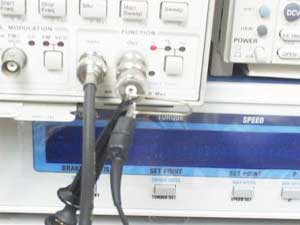
Figure 2 -
Recommended Setup of Function Generator Output
The better approach is to use a 50 Ω terminated
cable, as shown in Figure 3. Even better, especially for chip resistors, is to
use a GR line insertion unit to preserve the 50 Ω
cable environment.
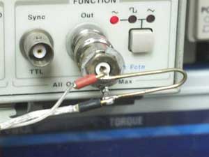
Figure 3 - Use
of 50 Ω Terminated Cable with Function Generator
3. Parasitic Series Inductance—Pulse Response Measurement
Parasitic Inductance
Measurement: Pulse Response Method
A better series-inductance measurement
technique uses a pulse generator. In the time domain, Rs can
be eliminated from its effect on the measurement, a big advantage over the
previous approach. Using the same setup as before, except with a pulse generator
as an open source, the generator voltage pulse rising transition is adjusted to
be 10 V in 50 ns, or 200 V/µs in this case. Then the source — still considered
to be a current source (because Rg >>
Rs) — drives the sense resistor with a current ramp of
 .
.
(The ÷ 2 is due to the 50 Ω termination divider.)
The inductance follows from the v-i relationship for inductance:
 ,
,
where vL is the constant inductor voltage due to the
current ramp.
The following waveforms were observed with the inductance driven by a
Tektronix PG508 pulse generator.
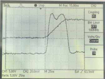
Figure 1
The top waveform (A) is the open-source voltage without a sense resistor; the
ch 2 waveform is the response with a resistor, though only approximately
time-aligned with the (stored) A waveform. (Note the ×1 setting for ch 2, which
is terminated with 50 Ω.)
The voltage, vo, steps up to vL, a value
of about 100 mV (on ch 2, at 20 mV/div). The current-ramp voltage drop across
Rs causes a ramp-up superimposed on vL,
which is negligible and undiscernible amidst waveform ringing. The pulse
flattens on top to a constant voltage, leaving (on ch 2) a constant-current
drive of Rs, producing about 6 mV (about ¼ div). The value of
Rs can be calculated from the voltage-divider formula, where
Vg (= 12.5 V) drives Rg = 25
Ω in series with Rs to produce about 6 mV
across it:
 .
.
For this measurement, the resulting value of Rs is about 24
mΩ, which is 4% less than the approximately 25 mΩ measured with an RLC meter.
The inductance is calculated from the measured voltage:
 ,
,
which is a reasonable value based on the geometry.
Several factors that limit the usefulness of this method are listed below.
Closure
It is difficult to measure the series inductance of
small-value resistors. An approximate value can be measured, however, using a
very simple setup with a pulse generator and an oscilloscope. This approach will
yield the small values not measurable with most RLC meters. A network analyzer
can provide more accurate measurements at a much higher price.
Copyright © Dennis L. Feucht, 2000
4. Example problem
Question:
We are looking for the following shunt resistors.
Current
(A) |
Voltage Drop
(mV) |
TCR
(ppm) |
| 40 |
100 |
10 |
| 1 |
100 |
10 |
Can you kindly suggest a
manufacturer?
|
Answer:
Current sense
resistors are sometimes called shunt resistors. While many people
think of a shunt as "a piece of wire with low resistance," there are
actually a number of considerations.
Small Values—First, a current sense resistor must be
large enough so that a reasonable voltage drop develops across it. On the
other hand, the resistance must be kept small, otherwise it dissipates too
much power. To obtain low resistance values, one has to use special metal
alloys. Commercially, one can purchase current shunt/sense resistors with
values in the range 0.0003–100 Ω, designed for
currents in the range 1–30,000 A.
Temperature Coefficient of Resistance (TCR)—Clearly the
questioner is concerned how the shunt resistance will change with
temperature, since this will directly impact the accuracy of any
measurements made. A quick examination of manufacturer's catalogs show
that typical TCRs of current shunt/sense resistors are in the range
100–700 ppm/°C, or equivalently,
0.01–0.07%/°C. A TCR of 10 ppm/°C (0.001%/°C) is a stringent requirement
by any measure. Most pure metals have much higher TCRs, but there are a
few alloys such as Manganin that have TCRs below 20 ppm/°C.
Inductance—If the shunt will be used to measure AC
current, then inductance may become an issue. Normally, one could safely
ignore the inductance of a piece of wire 0.5–1.0 inch long, even at
relatively low frequencies. However, since shunt/current sense resistors
have values in the milliohm range, even inductances in the order of 100 nH
can affect measurements. ChipCenter's Dennis Feucht explored the
inductance of shunt/sense resistors in a series of articles (see the References
below).
Thermal EMV—A current shunt/sense resistor normally
implies at least three different metals:
(a) copper wire or PCB cladding,
(b) lead/tin solder, and
(c)
the special low TCR alloy of the current shunt/sense resistor.
Whenever dissimilar metals are in contact, it is almost inevitable that
small EMVs are generated. This will be in the range of ± 2 µV/°C for the
metal-metal junction in current shunt/sense resistors.
Returning to the question, the table below shows that the questioner
wants:
(a) 2.5 mΩ, 4 W, and
(b) 100 mΩ, 0.1 W resistors.
Current
(A) |
Voltage
Drop
(mV) |
TCR
(ppm) |
Resistance
(mΩ) |
Power
(W) |
| 40 |
100 |
10 |
2.5 |
4 |
| 1 |
100 |
10 |
100 |
0.1 |
It is not clear
whether inductance is an issue.
One possibility would be the A-H type of current-sense resistors from
Istotek that are available in resistances of 0.001–100 Ω, are made
from Manganin foil with low (< 10 ppm)
TCR, and are rated at 10 W. Isotek offers online ordering as well. I list
a few other suppliers in the references below.
References
- Caddock
manufacturers a diverse range of precision resistors, including current-sense
resistors.
- Dennis Feucht, Making
Sense of Sense Resistors — Part 1: Temperature Effects,
ChipCenter.
- Dennis Feucht, Making
Sense of Sense Resistors — Part 2: Parasitic Series Inductance–Frequency
Sweep Measurement, ChipCenter.
- Dennis Feucht, Making
Sense of Sense Resistors — Part 3: Parasitic Series Inductance–Pulse
Response Measurement, ChipCenter.
- Empro
Manufacturing Company markets a wide range of Manganin (remember:
TCR for Manganin ~ 20 ppm/°C) DC current shunts.
- Isotek
Corporation markets specialized resistors, including current-sense
resistors.
- Ohmite is a
well-known manufacturer of a wide variety of resistors. Some
of their resistors may be used for current sensing applications.
- There are laboratory test-equipment
current shunts available, where the user programs a resistance value
in.
|