Opto-isolators
V2.05 2-Sep-2008
1. Introduction
Opto-isolators, or opto-couplers, are made up of a light emitting device,
and a light sensitive device, all wrapped up in one package, but with no
electrical connection between the two, just a beam of light. The light
emitter is nearly always an LED. The light sensitive device may be a photodiode,
phototransistor, or more esoteric devices such as thyristors, triacs etc.
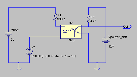
The cheapest kind have phototransistors. Below is a basic circuit diagram
using one of these types (4N25):
The output of this circuit simply follows the input:
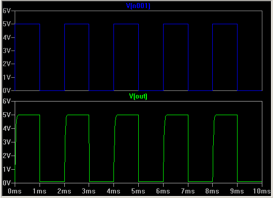
Note the slight curving of the square wave output. All opto-isolators will
only work up to a certain frequency. Some are much faster than others. Make
sure that the opto-isolator you use is fast enough for the signals you are
putting through it - more details in section 4. The reason the rise time is
slower than the fall time of the output waveform is that the rising edge is
due to the 4k7 pull-up resistor, which has to discharge the capacitance in
the opto transistor. If this needs to be speeded up, the 4k7 resistor value
can be reduced, at the expense of using more current when the output is low.
When the LED is driven with a current of 10mA or so, it shines onto the
phototransistor, which then starts to conduct (turn on). This takes the
output voltage low. However much electrical noise is on one side, it can
never be transmitted over to the other side. We may use an opto-isolator
to send PWM signals from the low-power electronics side to the MOSFET drivers
on the high-power side, and we may use them to transmit information from
the high- power side back to the low-power side.
To complete the isolation of the low and high power sides, each must
be powered by a completely separate battery. The high power side will be
powered by the main 12v or 24v battery. The low-power side can be powered
by a much smaller battery, maybe 6v.
2. Opto-isolator parameters
If you open a datasheet for an opto-isolator in a separate browser window,
we can go through some of the parameters and describe what they mean. Click
here
to open a datasheet for the Sharp PC123 in another window, because we will
be referring to it.
Collector-emitter voltage
This is the maximum voltage that can be present from the collector to the
emitter of the receiving phototransistor (when it is turned off - no light)
before it may break-down.
Creepage distance
This is physically how far a spark would have to travel around the outside
of the package to get from one side to the other. If the package has contaminants
on it, solder flux, or dampness, then a lower-resistance path can be created
for noise signals to travel along.
Forward current
This is the current passing through the sending LED. Typically, an opto-isolator
will require about 5mA to turn the output transistor on.
Forward voltage
This is the voltage that is dropped across the LED when it is turned on.
Most normal diodes drop about 0.7v, but with LEDs it is typically 1 - 2
volts.
Collector dark current
This is the current that can flow through the output phototransistor when
it is turned off.
Collector-emitter saturation voltage
When the output transistor is fully turned on (saturated), this is the
voltage there will be between the collector and emitter.
Isolation resistance
This is the resistance from a pin in the input side to a pin on the output
side. It should be very high.
Response time
Thee rise and fall times are the times that the output voltage takes to
get from zero to maximum. The rise time is very much dependant on the load
resistor, since it is this that is pulling the output up. Therefore this
value is always quoted with a fixed load resistance. Note however that
the value, 100 Ohms, is much less than you are likely to use in practice.
This is another of the manufacturer's attempts to make the product look
better than it is!
Cutoff frequency
This is effectively the highest frequency of square wave that can be sent
through the opto-isolator. It is actually the frequency at which the output
voltage is only swinging half the amplitude than at DC levels (-3dB = half).
It is therefore linked with the rise and fall times.
Current Transfer Ratio (CTR)
This is the ratio of how much collector current in the output transistor
that you get given a certain amount of forward current in the input side
LED. It is affected by how close the LED and phototransistor are inside
the device, how efficient they both are, and many other factors. In fact
it is not a constant but varies wildly with LED forward current as we will
see.
2.1. The graphs
The graphs are essential to see how the device actually performs,
rather than how the manufacturer wants you to think it performs on initial
reading of the front page parameters! We'll take an example and work it
through the graphs.
-
The first few graphs on power dissipation are not really of any great interest
to us. They are more useful for people designing low-power consumption
circuits.
-
Fig 7: The Current Transfer Ratio vs. Forward Current is a useful graph.
This shows how the CTR varies wildly. In our design, we will start with
a required collector current for the output phototransistor. From that,
we can calculate how much forward current is required in the LED to produce
it using this graph. For example, if we required 10mA of collector current,
then we must follow the line of this graph until the forward current times
the CTR is 10mA. This occurs at about If=6mA / CTR=180%.
-
Figure 9 shows how the CTR will be affected as the electronics get hot,
which they are bound to do as the motors and MOSFETs start dissipating
power. It shows at 100 degrees the CTR has derated to about 60%, so we
should re-estimate our required LED forward current based on this. Assume
the % values for CTR in figure 7 are only 60% of what they are shown, then
we need about If = 10mA, to get a collector current of If x CTR x 60% =
10mA x 180% x 60%.
-
Fig 6: Forward Current vs. Forward Voltage. This is the LED diode curve.
We now know we need 10mA of forward current, and from this graph we can
see that the LED will drop about 1.1 volts at 50 degrees C. If we power
this LED from the output of a CMOS device (0 to 5 volts), then we can calculate
the series resistor required: R = (5-Vf)/If = (5-1.1)/10mA = 390 Ohms.
-
Figure 8 allows us see the collector-emitter voltage that will be present
when the output phototransistor is turned on. Follow the If = 10mA line
until it crosses the 10mA Ic of the vertical axis. The Vce(on) is about
1 volt. This is the voltage we will have at the output when the light is
on. We can now calculate the load resistor, Rl, that we require from the
collector to battery positive, Vb. This is Rl = (Vb-Vceon)/Ic = (12-1)/10mA
= 1.1k.
-
Figure 11 shows how much current will flow through the phototransistor
when the LED is off. Worst case, when hot, is about 10 microAmps. With
this current, the output voltage will be Vo = Ic(off) x Rl = 0.00001 x
1100 = 0.01V. This is how much lower than Vb the output will be, i.e. 12
- 0.01 = 11.99V. This is the output voltage with no light input.
-
Figure 12 allows us to see how fast a signal the opto-isolator can cope
with given the conditions that we have now laid down. The load resistor
is 1.1k, follow the tr and tf lines to get tr=25, and tf=20 microseconds.
Now the fastest signal will be when the output rises as soon as it has
fallen, and falls as soon as it has risen. A complete cycle takes 20+25=45
microseconds. This is the minimum time that one pulse can take. For the
PWM signal, it is the thinnest pulse. If you want the PWM signal to increase
in steps of, say, 5%, so there are 20 discrete speed settings, then one
5% slot will be 45 microseconds, so the complete frequency will be 20 slots
worth, or 900 microseconds, which is a frequency of 1.1kHz.
This has shown how a design is developed using the given parameters from
a datasheet.
3. Types of opto-isolator
The opto-isolator in the example above was a simple photo-transistor output
type. These are the cheapest types, although they're not always the most
useful. For a start, the LED required 10mA of forward current. If you are
driving it from a microcontroller, it may not be capable of sinking that
much current, so you would then need a transistor to boost it. In this
case, you may better off using a logic to logic opto-isolator. These require
a 5 volt supply and will accept a logic level input. The output may also
be logic-level, or it may still be open-collector like the example above.
Logic level opto- isolators generally can be run at much higher frequencies.
10Mbits per second is typical.
4. Frequency and Rise & Fall times
We are likely to be driving at least some of the opto-isolators with PWM
signals for speed control of the motors. What frequency are these PWM signals,
and will the opto-isolators be able to cope with them?
The PWM signals are generated elsewhere in your circuit of course, so
you may already have decided what frequency they will be. This frequency,
together with the number of discrete speed steps that you have, determines
how fast the opto-isolator must be. The diagram below show a PWM signal
with 12 discrete speed steps, with a 1/12 level signal (signal A). This
means the signal is high for one twelfth of the time:
The number of speed steps may be greater. Most microcontrollers with
PWM outputs use an 8-bit register, giving 256 discrete speed steps.
The frequency of this PWM signal is the reciprocal of its total time
period, tp. Fpwm = 1/tp. However, any
circuit that transmits this must be able to respond to the single pulse.
To respond to this, it must be able to respond to a frequency rather higher
than Fpwm, that shown in orange in signal B. The frequency of
this signal is
The 16 in the equation comes from the number of discrete steps, so in
general, we can say that if we want n discrete steps, the opto-isolaator
must be able to handle a frequency of


Most opto-isolator datasheets quote the rise and fall tmes of the opto-isolator
outputs rather than a maxmum frequency. How can we use these values? The
diagram below shows a more realistic signal from an opto-isolator.
In this diagram, the rise and fall times are shown equal, but
they are often not - especially with open-collector or open-drain type
optos where an external pull-up resistor controls the rise time. It can
be seen from this and the previous equations that

Therefore, if we are given an opto with defined rise and fall times,
we can work out:
The maximum frequency for n discrete speed steps:
The maximum number of speed steps for a PWM frequency of FPWM:
Example
Question
The Hewlett Packard (Agilent) HCPL-3120 optocoupler has the following
parameters:
tr = tf = 0.1μs
Given that the PWM frequency has been set at 25kHz to be above audible
range, what is the greatest number of discrete speed steps that can be
attained.
Answer
Using the equation
n = 400. Therefore n 8-bit PWM register with 256 discrete steps would
work fine.
Note that even if we drove this optocoupler with more than 400 steps,
all that would happen is that there would be no measurable difference between
a setting of, say, 650, and 651, and if a 1024 discrete step PWM signal
was set to a level 1/1024 (signal high for one 1024th of the
time), then the opto would not respond, and the effective level would be
zero.
-
More complicated PWM signals
This next diagram shows a PWM signal with 12 discrete steps, set at 3/12
level:
The three segments during which the signal is high are not necessarily
next to each other. This signal will generate a smoother resultant speed
in the motor than if all three pulses were next to each other. Some PWM
generators may generate a signal like this, some may have all three pulses
next to each other, in which case the required response time of the optocoupler
need not be so high.
5. Some links to opto-isolator manufacturer's pages
Avago (plastic)
Avago (hermetic)
Sharp
Toshiba
Back to Speed Controllers
Back to main index

