V1.00 03-Sep-02
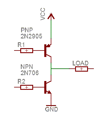
To be able to switch one end of a load (e.g. a motor) to a low voltage or a high voltage, you need two transistors - one to switch it high, one to switch it low. These are orientated as shown below:

In this diagram I've used a bipolar NPN transistor at the bottom and a PNP bipolar at the top. This arrangement is called a half-bridge. The left hand end of the load can be pulled high by turning on the PNP transistor (by pulling its base low), or it can be pulled low by turning on the NPN transistor (by pulling its base high).
The PNP transistor that pulls the load high is called the high side transistor, and it performs high side switching.
The NPN transistor that pulls the load low is called the low side transistor, and it performs low side switching.
Where does the other side of the load go? (you may have asked). If you had a three rail power supply, for example, +12V, 0V, and -12V, then the half bridge could switch between +12V and -12V, and the other end of the load could be attached to the 0V rail. Then the load would either have +12v or -12v across it. However, to make a power supply like this from 12v batteries, you would need two wired in series, with the 0V rail being the connection between them:
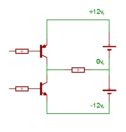
This can be achieved with only one battery by switching the right end of the load low when the left end is high, and the right end high when the left end is low, so the voltages on each end swing up and down like a see-saw:
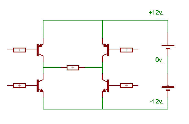
This arrangement is called a full bridge.
Transistors come in two flavours, whether they are bipolar or FETs - N and P. This is because the silicon is 'doped' with other chemicals. Doping with one type gives N-doped silicon, and doping with another gives P-doped silicon. Although both types are used in both N and P transistors, the channel that the current flows through is only one type. N channel devices (NPN bipolars and N-channel FETs) can carry more current than P-channel devices (PNP bipolars and P channel FETs). Therefore, it is better to use only N channel devices in the bridge:
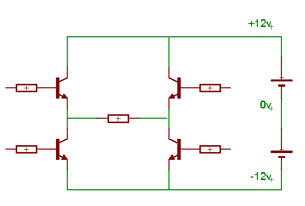
However, the problem now is that to turn the top NPN transistors on, we need to take the base resistor voltage higher than the +12V power supply. This is awkward, but is worth the trouble since the NPN transistors are so much better than PNP. Bridge driver chips often have the higher-voltage generating circuits built into them to make it easier.
The bipolar transistors shown in the previous circuits can be replaced with MOSFETs quite easily. The PNP can be changed for a P-Channel MOSFET, and the NPN for an N-channel MOSFET:
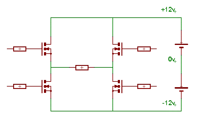
The same applies for turning on the top MOSFETs - the voltage at the gate terminal must be taken higher than the power supply rail, typically 10V higher.
Often, MOSFET drivers consist of just a half bridge circuit. Two of these can be used together to make a full bridge circuit, and so they are often packaged two-to-a-chip. These can be designed so that when the control input goes high, the output (the join between the two transistors) goes low. For example, a bipolar transistor based half-bridge circuit is shown below:
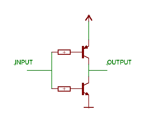
Since the output is the opposite of the input, this cirucit is inverting. If you put two of these into one chip, you have a dual inverting half bridge driver.