Solenoids and Actuators
V2.01 18-Mar-03
1. What is a solenoid?
A solenoid converts electrical power into linear mechanical power. Whereas
a motor converts electrical power into a continuous rotational mechanical
power, a solenoid has a finite, generally only short, mechanical movement.
Solenoids are normally built by winding a coil of wire around a moveable
soft iron core. When a current is passed through the coil, the core moves
towards the centre of the solenoid. The current can be DC, AC, or a pulse-width
modulated waveform that is partly DC and partly AC.
This page should help you if you are using bought-in solenoids in your
robot, or if you are trying to design your own solenoid or electromagnetic
actuator.
2. Magnetic circuit theory
Before describing how solenoids work, it is necessary to know a little
about magnetic circuits. Magnetic circuits are similar to electric circuits
in many respects. Letís introduce some terms:
Magneto-Motive Force (MMF)
This is the equivalent of electro-motive force (EMF or voltage) in an electric
circuit. Itís units is Ampere-turns (At). A coil carrying I amps
with n turns will generate an MMF of nI Ampere-turns. It
is designated by the fancy letter F.
Flux
Magnetic flux is similar to current in an electric circuit. Itís unit is
the Weber (Wb), and it is designated by the Greek letter Phi (Φ
Flux density
The flux density is the flux divided by the cross sectional area of the
magnetic conductor that the flux is transported in. Itís unit is the Weber-per-metre-squared,
or Tesla (T), and it is designated by the letter B.
Reluctance
This is the ratio of MMF to Flux in the magnetic conductor, and so is equivalent
to electrical resistance. It is proportional to the length of the path,
and inversely proportional to the cross-sectional area, just like resistance.
Itís unit is the Ampere-per-Weber, and it is designated by the fancy letter
R.
Permeability
Permeability is a bit like reluctance. It describes how much a material
resists magnetic flux flow, and so is equivalent to the resistivity of
electrical conductors. It has units of Tesla-metres-per-Ampere, and is
designated by the Greek letter Mu (μ).
The permeability of free space,
μ0,
has a fixed value of 4πx
10-7.
Relative permeability
This is the permeability of a conductor relative to that of free space.
For example, soft iron has a relative permeability of around 6000, which
means its actual permeability is 6000 x 4πx
10-7 = 0.0075 Tm/A. It has the symbol μr.
Now we have some terms to deal with, letís examine a magnetic circuit.
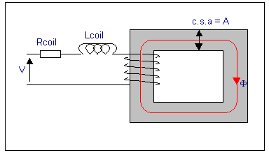
This is a solid iron square ring with a cross sectional area of A
metres2, and an average path length of L:
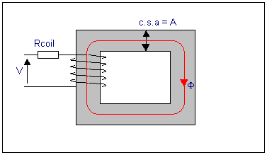
The coil has a resistance of Rcoil, which is shown as a lumped
resistance, so the coil current for a DC supply, V, is I = V/Rcoil.
The coil generates an mmf of NI ampere-turns, which drives a flux
Φ around the iron. Some simple equations can be written to describe this:
The mmf generated by the coil, is given by:

The reluctance of the iron is given by the equation:

where L is the average length of the path, and A is the cross sectional
area. Note that the symbol μ is used a simple term to cover both
μ0 and μr.
The flux generated is then:

and the flux density in the core is:

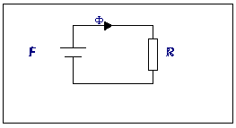
An equivalent electrical circuit can be drawn to represent this:
The inductance of the coil is given by the equation:

Now what happens if an air-gap is introduced:
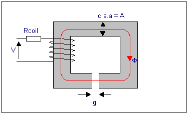
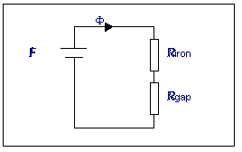
The reluctance of the iron is still almost the same (it is nearly the
same length and same csa), but there is an added reluctance in series,
that of the airgap. The relative permeability of air is 1, so the reluctance
of the airgap is

Now the electrical equivalent circuit looks like this:
2.1. Forces in magnetic systems
It is a feature of magnetic circuits that there is a force on any component
that if moved, will reduce the reluctance (or increase the inductance,
same thing) of the circuit. Therefore in the previous diagram, there is
aforce between the ends of the iron core each side of the airgap. If the
iron could move, the ends would come together to eliminate the airgap.
One way of understanding this is that the coil makes the iron into an electromagnet,
with an N pole at one end and an S pole at the other, across the airgap.
These two poles, being opposite, attract each other.
3. DC, AC, or PWM drive
When you buy a solenoid, it will be rated for DC (continuous current) drive,
pulse-width modulated (PWM) drive, or AC drive. What do these mean? The
waveforms below show examples of these drive signals:
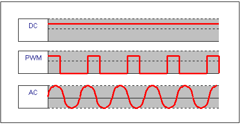
DC is obviously the simplest to use. AC is generally only useful if
you are using it from an AC supply derived from the mains. PWM is a lot
harder to generate, but is the best to use.
Why is PWM best?
In the previous magnetic ciruit diagrams, just the resistance of the coil
was shown. If the driving voltage is DC, then thatís all there is to worry
about. However, the coil also has a very large inductance. Remember from
the equation written previously:

The inductance of the coil is dependant on the reluctance of the magnetic
circuit. When an airgap is introduced, the total reluctance increases,
and so the inductance decreases. If the voltage source is AC, or PWM which
is a micture of AC and DC, then the inductance will also resist the flow
of current. The impedance (like resistance) of an inductor is given
by the equation:

where f is the frequency and L is the inductance. The
impedance of the whole circuit, including R is:

As the resistance, frequency, or inductance increases, the impedance
increases, and the current will fall.
Letís have a look at what a real solenoid looks like. This is a lengthwise
cross section through a cylindrical solenoid:
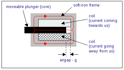
The coil creates an MMF which drives flux (shown in red in the diagram)
left through the plunger, then around the frame of the solenoid over to
the right hand side, then through the airgap and back into the plunger.
The reluctance of this path is mostly made up by the airgap.
When the plunger is out, as shown in the diagram, the reluctance is
quite high. When current is applied to the coil, the plunger moves to the
right, and the reluctance decreases. This is an example of what was said
before about forces in magnetic systems Ė they always act to reduce
the
reluctance, or increase the inductance. Eventually, the plunger
will collide with the frame on the right hand side, and the airgap will
be zero, and the reluctance will be at a minimum.
What happens to the inductance of the coil as the plunger moves. Remember
the equation for the coil inductance:

With the plunger fully to the left, the airgap is quite wide, and so
the reluctance is quite high, so the inductance is low. Remember from before
that the impedance of the coil to the supply voltage is dependant on the
inductance of the coil:

The current in the coil is simply the voltage divided by the impedance
(Ohmís law):

With the plunger fully out, the inductance is low, and so the current
will be quite high. As the plunger moves in, the inductance increases,
and the current falls. This high initial current is called the "inrush
current" since it only last for a short time until the plunger is fully
in. The inrush current is useful, because it allows a large current to
start with which generates a large force to get the plunger going. Once
the plunger has pulled in, less force is required to just hold it there,
and conveniently, there is less force because the current is now lower.
This is why PWM drive is the best for solenoids. A solenoid designed
for PWM drive will have quite a low coil resistance. If DC was applied
to it, the coil would heat up and burn out. It is the inductance of the
coil on a PWM signal that restricts the current to safe values. Of course
this means that if for any reason the plunger gets stuck in the "out" position,
where the inductance is low, the coil may burn-out.
4. Force-stroke curves
When you are selecting a solenoid to buy, the datasheet will always have
a force-stroke curve. This shows how much force you can expect the solenoid
to be able to pull or push given how far out of its position it is. Often
manufacturers sell the same mechanical solenoid with a variety of drive
waveforms Ė DC or PWM. As described previously, the PWM drive solenoids
have much lower resistances because they rely on the inductance to limit
the current.
Letís have a look at an example force-stroke diagram for the BLP
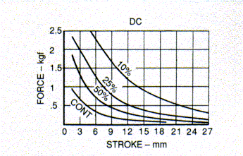
There are four curves all superimposed on the same graph. Notice that
the solenoids designed for shorter on-timesa in PWM mode have much larger
forces due to the geater currents that they can carry.
As the plunger approaches the end-stop (stroke approaching zero) the
force is at its maximum. The equation that governs the force-stroke curve
varies depending upon the physical construction of the solenoid. Most are
based on an inverse square law however:

where r is the radius of the cylindrical plunger. This equation
would indicate that the force would be infinite when the stroke is 0mm.
This is obviously impossible, but this equation is only an approximation
and neglects the reluctance of the iron, and the fact that some of the
magnetic field will leak out into the air around the iron Ė "fringing effects".
It also assumes a perfect cylindrical solenoid Ė most are not built that
way.
In fact, often the force can be nearly independant of the stroke distance,
andcan tend towards the much simpler equation:

where A is the cross sectional area of plunger and B is the flux denisty
in the plunger.
These equations are only approximations. To find the actual force you
will need to refer to the solenoid daatsheet and examine the force-stroke
curves, or if it is a solenoid of your own manufacture, you can measure
the force at each position and plot your own curves.
5. Plunger end styles
You may wonder how the shape of the end of the plunger can have any effect
on the force. Remember though that the coil MMF drives a flux, Φ,
through the iron. However, the force is dependant on the flux density,
B, and so if the area that the flux is passing through is decreased, the
flux density is increased, since

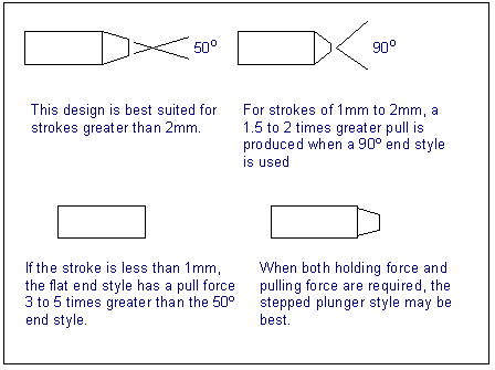
Therefore, the plunger of the solenoid may have a chamfered look as
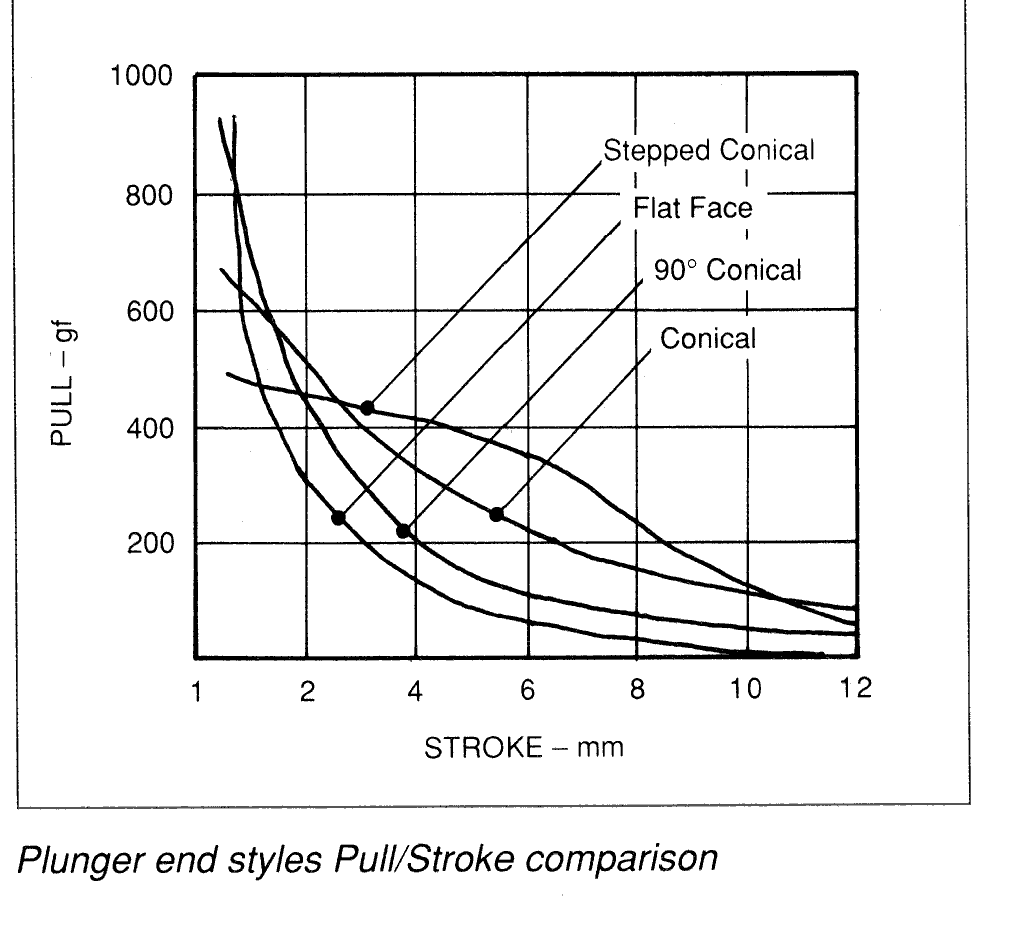
in the diagrams below. Generally, doing this increases the pulling force
at larger stroke lengths. When the stroke is 1mm or less, then a flat plunger
produces a higher force.
The following force-stroke graph shows the effects of the differing
plunger end styles on the curve shape:
6. Latching solenoids
Once the plunger has reached the end-stop (stroke = 0mm), it will remain
there as long as current continues to flow. The current may be reduced
if required to hold it there, probably by reducing the PWM ratio. However,
most commercial solenoids have a spring fitted so that if the current is
turned off completely, the plunger will return to its starting point, at
maximum stroke. If you want the solenoid to stay at its zero stroke position,
you must maintain the current. This can be quite wasteful of power if it
to remain there long. In this case, a latching solenoid is the best
option.
Latching solenoids integrate permanent magnets into the design which
hold the plunger in the zero stroke position, even when the coil current
is removed. To return the plunger to its extended position, a pulse of
coil current is applied in the opposite direction to push the plunger
away from its end-stop. This means that a latching solenoid driver must
be able to force current through the coil in either direction. This is
usually achieved using an H-bridge arrangement similar (although generally
lower power) to those used in
speed
controllers.
7. Driving solenoids
If you are going to drive your solenoid with DC, then it is very simple.
Just switch the DC supply to it with a relay or transistor, and the solenoid
will fire. However, if you are going to use PWM, then a solenoid driver
chip is the best solution.
7.1. Flywheel diodes
However the solenoid is driven, flywheel diodes are necessary. The large
inductance of the coil can cause large voltage spikes to appear across
the switching element (relay or transistor doing the switching), unless
the current flowing through the coil is allowed to dissipate slowly.
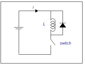
When the switch is closed, the current flowing down through the coil
is limited by the resistance of the coil. Inductors do not like the current
flowing
through them to change quickly, and they will generate a voltage of their
own to stop this happening. Therefore when the switch is opened, the inductor
generates a voltage to make the current continue down through the coil.
Because the switch is now opened, the current flows up through the diode,
and back round into the inductor. The diode is called a "flywheel" diode.
7.2. Suppression
Even with the diode in place, a solenoid can generate a lot of electromagnetic
noise spikes. These may be suppressed using snubber networks if required.
A separate page on snubber networks can be found
here.
7.3. Solenoid driver chips
By far the easiest way of driving solenoids, especially when using PWM,
is to use a solenoid driver chip. These are available from several manufacturers
and come in a large variety of forms. They integrate all the components
for generating a PWM waveform, and also often have features such as an
initial DC pull-in, short circuit protection, integrated flywheel diodes,
and multiple drivers in one chip.
DC pull-in
Because the pull-in current required is much larger than the holding current,
many chips drive a short DC pulse to strat the plunger moving, before driving
with the PWM waveform.
Short-circuit protection
If the output of the solenoid driver is short-circuited for any reason,
a solenoid driver chip with this feature will turn off the output to save
frying itself. Also remember PWM solenoids take a very large current when
the plunger is at maximum stroke. If it is stuck in this position, it can
burn out. The short circuit protection may be able to protect against this
too.
Integrated flywheel diodes
This is often intgerated into the chip to save on external components.
Multiple drivers
Solenoid drivers are available that integrate a shift register and solenoid
drivers so that up to eight solenoids may be controlled from a synchronous
serial interface. If you have a microcontroller on your robot, this is
a very pin-efficient method to drive all your solenoids using just three
control pins. The shift register in some can also read the state of the
output so short circuit conditions can be read back to the microcontroller
and an error condition entered.
Links to some solenoid driver datasheets
ST (SGS Thomson)
PWM
drivers for solenoids
L6213
single solenoid driver
L9822N
Octal serial solenoid driver
TI (Burr Brown)
DRV102
TPIC2603
Allegro
UDN2962
Dual Solenoid/Motor Driver Pulse-Width Modulated
Intersil (Harris)
CA3282
Octal Low Side Power Driver with Serial Bus Control
The companies listed manufacture many more solenoid drivers, visit their
sites by clicking on the names and use their search facilities for the
keyword "solenoid".
8. Designing your own solenoid or actuator
There are some simple rules to follow if you are trying to design your
own electromagnetic actuator.
8.1. Increase the MMF
Your actuator will be stronger of the magnetomotive force (MMF) is maximised.
The MMF is the number of ampere-turns the coil is generating, so this must
be maximised. If you want to increase the ampere-turns, simply adding more
turns of wire will not help. If you double the number of turns, then the
resistance of the coil will also double, and so the current will be halved.
Therefore, the total ampere-turns will be the same. To increase the ampere-turns,
you can:
-
Use wire of a lower resistance Ė thicker wire.
-
Split the wire into n sections and wire these in parallel.
-
Use more than one coil.
If you have a fixed volume into which the coil is going to be placed, increasing
the wire thickness will not help either, because fewer turns of wire will
fit into the space. Therefore the best solution is to split the wire up
into several sections and connect the sections in parallel. For example,
if you have a wire 10 metres long which is 12?, then splitting it into
two sections and wiring in parallel gives a coil of resistance 3?, which
would pass a current four times larger. In general, if the wire is split
into n equal sections and wired in parallel, the ampere-turns will be increased
by n2.
It is best to solder the wires in parallel first, then wind them onto
the coil former, to make sure that they all wrap round in the same direction!
8.2. Decrease the reluctance
The force produced is proportional to the flux density in the magnetic
circuit. This can be increased either by increasing the MMF as above, or
decreasing the reluctance. The flux passes best in iron, so any part of
your mechanical arrangement that you want flux to flow through should preferably
be iron. Of course, at least some part of the magnetic circuit will be
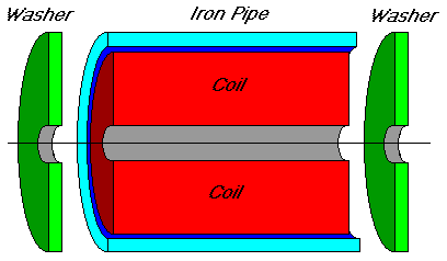
through air, but this should be reduced as much as possible. For example,
a toroidal coil can have an iron tube around it with washers placed either
end so most of the magnetic flux passes through the iron before going through
the air in the centre of the toroid.
8.3. Get the opposing spring constant right
As the electromagnetic force pulls the plunger in one direction, it is
likely that you will fit a spring pulling it back in the other direction.
The force that this spring exerts must be carefully chosen so that itís
force-stroke graph matches that of the solenoid. Springs have a linear
force-stroke characteristic, governed by the simple equation
force = spring constant × extension (stroke)
By choosing the appropriate original length of spring and spring constant,
a suitable opposition force to that generated by the coil can be chosen.
8.4. Relay contacts
If you are designing a heavy duty contactor, or relay, which is going to
switch large DC currents, then the material used for the electric contacts
is important. As the contactor opens, it is likely that sparking will occur
across the contacts. These sparks erode the contact material, and can cause
the contacts to stick next time they are shut. Tungsten or silver alloys
are generally used in industrial applications.
A datasheet of suitable materials can be found here.
9. Links & Books
Basic electromagnetic theory pages
http://theory.uwinnipeg.ca/physics/mag/node1.html
http://www.gaussbusters.com/ppm93.html
http://www.acesinternational.org/Secrets%20&%20Tips%20Electronics3.htm
Magnetic design
http://www.dextermag.com/magnetic.htm
Non-technical Ė the solenoid as a magnet
http://www.arts.richmond.edu/~rubin/pedagogy/132/132notes/132notes_65.html
Effect of surrounding a coil with iron:
http://www.oz.net/~coilgun/theory/externaliron.htm
Solenoid manufacturersí product index, links to datasheets:
BLP:
http://www.blpcomp.com/fmproductsidx.htm
Trombetta:
http://www.trombetta.com/defaultframeset.asp?ShowContent=solbasics
Mechetronics:
http://www.mechetronics.co.uk/
Emessem:
http://www.magnet-schultz.com/solenoid.htm
Relay technical links:
http://www.pandbrelays.com/application.stm
Books:
Linear
electric actuators & generators
I. Boldea and S.A. Nasar, Cambridge University Press, 1997


![]()
![]()
![]()
![]()

![]()

![]()


![]()

![]()
![]()

![]()
![]()
![]()

![]()
![]()
![]()


