Hi Paul,
I wanted to thank you for your document regarding 4094 shift and store registers. I found it extremely useful for my PinMAME-HW project. Basically, with this project, I am controlling pinball machines with PinMAME, a pinball machine emulator, which eliminates the need for the old, unreliable custom boards. :) I probably wouldn't have been able to do it without your document.
I did have one question for you.... You are using R2 (47k resistor) to put the outputs into tri-state.... but how do you do this with a 4094? The 4094, as you know, doesn't have a Master Reset.... so with the 4094, what do I do? Just connect the resistor between +5VDC and Output Enable? I am powering all my 4094's with +5VDC.
Thanks!
Hi,
For the 4094, you will need R2 to pull the Output Enable pin (pin 15) low. This will cause all the outputs of the shift register to go tri-state. Now you also may need to pull the shift register outputs low or high so that when the line is tristate, whatever it is driving does not waggle about.
Here are three possible situations:
1. If the output line is driving something that you don't care whether it "waggles about in the wind" for a couple of milliseconds while the microcontroller is powering up, for example, light bulbs, then you won't need to do anything to the line.
2. If the output is driving another digital logic chip, and if the line waggled about for a few milliseconds and the result may cause problems, for example, the other chip is a counter or a complex chip that requires the line to be steady, then fit a pull-up or pull-down resistor to the line.
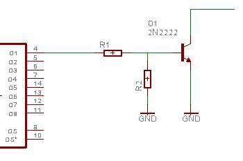
3. If the output is driving a transistor switch, for example, something like this:
Then R2 must be fitted to make sure the transistor is off when line Q1 is tristate.
One other point, I strongly suggest that you use 74HC devices rather than the old HEF4xxxB chips, as long as your power supply is always 5v or less. The 74HCs are better all round, faster, lower current, higher output drive, better input noise rejection, and far less prone to latch-up. The only advantage the 4000 series has is the power supply range up to 15V. They are pin-compatible so you can just plug the new device into the 4094 placement.
Hope that helps!
cheers,
paul
Thanks for the excellent suggestions with diagram, Paul! I am using the 74HC4094s. They are working great!
The problem that I'm having is that the PC's parallel port keeps the OE line high while Windows is booting up. My program can't take control of the 4094's until the Windows bootup process is completed. I don't care about the lamps I'm driving, but for my project, I do have 7 higher voltage solenoids (43VDC) for the flippers, drop targets, and outholes that I don't want to remain on too long otherwise it could burn the coils. These are transistor driven.
So if I will try using a 47Kohm transistor just as you have suggested in the diagram below.... But I'm not sure what you meant by this: "Then R2 must be fitted to make sure the transistor is off when line Q1 is tristate."
Is there something I need to do in addition to connecting the resistor as seen in the diagram below?
Thanks so much for your help!
The whole situation is a lot harder if the microcontroller is a PC with Windows. Whereas a microcontroller may take a few tens of milliseconds for the crystal to start oscillating, Windows could take minutes!
Is the parallel port definitely pulling it high, or is it just drifting high? Try putting a pull-down resistor of 47k or so and see if that makesa difference.
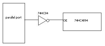
Otherwise, if all the parallel port lines are high while Windows is booting up, why not invert the line, and put an 74HC04 inverter in the path between the parallel port and the 74HC4094. Then OE will be held low until you are ready to take it high by taking the parallel port line low:
cheers,
paul
Awesome! Thanks a lot Paul.... I thought something like that would be in order....but I didn't know what I needed to invert the OE data line! I think this will work. When I turn on the PC, the OE line goes on and stays on until I take control of it with the software.
I will order some 74HC04's and give it a try.
Thanks again
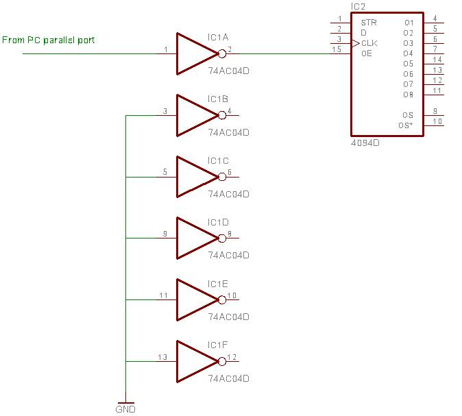
If you are using only one inverter gate in the 74HC04, make sure the inputrs to the other 5 gates are tied high or low. This stops them waggling about and causing the IC to pull more current. i.e.
cheers,
paul
That did the trick. I installed a 74HCT04 last night. It works perfectly. Now, the lamps and solenoids do nothing until the software initializes.
Thanks so much for your help!