
Car starter motors offer several advantages over other 12 Volt DC motors available to the roboteer, including very low cost (there are hundreds in every scrap yard!), a very high starting torque, and ruggedness. In contrast, there are some disadvantages that need to be overcome before they can be used in a typical robotic application. Before going into the detail of how they can be used, let’s examine the properties of the small DC series field motor.
All motors require two magnetic fields, one produced by the stationary part of the motor (the stator, or field), and one by the rotating part (the rotor, or armature). These are produced either by a winding of coils carrying a current, or by permanent magnets. Car starter motors do not generally use permanent magnets (although some do).
The motor I will describe here is from a 1985 Ford Fiesta 1.4L. This is a fairly typical motor, and most other motors are very similar. This car is very common in scrap yards, so if you want to stick with the same motor I used you shouldn’t have too much trouble obtaining them. I would like to thank WJ Dijkstra for providing the excellent photographs of the dismantling process.
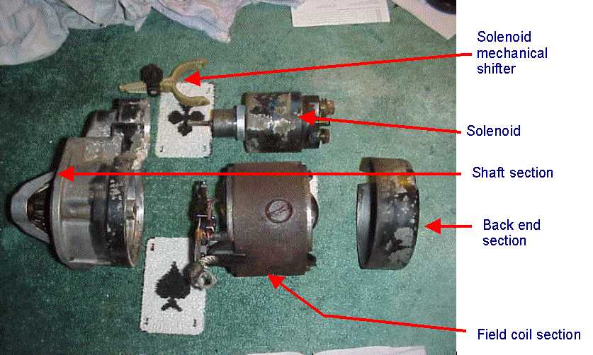
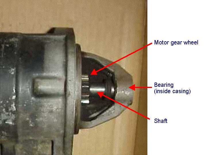
Let's first have a look at the motor as you buy it from the scrap yard:
The main parts are identified in the diagram. The outer case is made from three sections. The left hand section holds a bearing, and supports the back end of the shaft. The centre section holds the field coils in place, and the front section, which is made from cast aluminium, holds the front bearing, and shrouds the shaft gear wheel.
Let's take it to pieces! The first thing you'll need is spanners and screwdrivers of the correct size, and plenty of WD40! At the back end of the motor there is a small end cap held in place by two small screws. Take this off. Next there are three long retaining bolts which run the entire length of the motor, shown in the diagram. These shouldn't be too hard to undo - take them out completely. Now the three sections of the casing should come apart. You will probably need to hammer a screwdriver or chisel in the crack between them and force them apart if they are bunged up with oil and rust. This should allow you to get all the separate parts out, which should look something like the following:
The solenoid on the side of the motor is not needed, and once taken to pieces can be discarded, (it may be useful in another part of your robot). The last diagram shows all the stator parts (non-rotating parts). The rotor looks like this:

While the the motor is apart, it is a good idea to clean the commutator and brushes with WD40, to reduce the resistance Rb.
The first thing to modify will be the case at the front (business) end of the motor. Here there is a gear wheel, which can move up and down the shaft a little, which is half covered by shroud on the outer casing. If, like me, you are going to weld a sprocket onto the shaft, this shroud should be sawn off with a hack-saw. The brass bearing at the end of the shroud should be kept so you can remount it on the frame of your robot (the motor should not be used without this end of the shaft securely in the fixed bearing). Just pop the bearing out of the casing.
Now the electrical part must be modified. The centre section should look like this:

You should be able to trace the incoming wire which goes through the outer case (through a rubber or plastic grommet), and onto the field winding. At the other end of the field winding, it attaches to two of the four brushes. The current then goes through the commutator segments, through the rotor, back through the commutator segments and onto the other two brushes, where it eventually attaches to the motor casing (negative earth). We need to cut the wire between the field winding and the brushes:
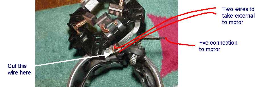
Both resulting ends of this wire need to be taken out through the casing. Drill two holes in the rear casing, wherever it is convenient. Note that these holes will need rubber grommets fitting so the wires do not short against the casing. Using as thick wire as you can obtain (Maplin CW71N earth bonding wire is cheap), attach the wire to the two ends of the cut wire, by soldering, or spot welding. Pass the wires through the newly drilled holes. You should now have three wires coming from the motor:
How do these wires correspond to the circuit diagrams shown in the speed controllers page? The following diagram explains:
The motor can now be connected to your speed controller as shown in the following diagram. Note that the current always passes through the field coil from left to right, but the speed controller is able to chop and reverse the current going through the armature coils. Thus the motor is now fully reversible.
If the starter motor you are working with has more than one field coil, they may be connected in parallel, and fitted in the same position as shown in the diagram above.
Now we must make the shaft on the front end of the motor accessible. You must first decide how you want to fix you sprocket or gear wheel to the shaft, and how you want the front motor bearing to be positioned.
You may want to weld the sprocket or gear wheel to the shaft. This may or may not be an easy welding job, and the strength of the result will depend very much on your welding ability, and the exact metallic composition on the shaft and sprocket/gear wheel. You will also have to extend the shaft, or retract the front bearing and casing to be able to perform the weld.
Alternatively, you may want to machine the front section of the shaft with a flat to take a cotter pin, or machine it fully square to take a square-bore sprocket or gear wheel. Grub screws are not a realistic option due to the very large torques that will be present, unless a hole is drilled all the way through the shaft and the grub screw is fed right through the gear wheel hub and motor shaft.
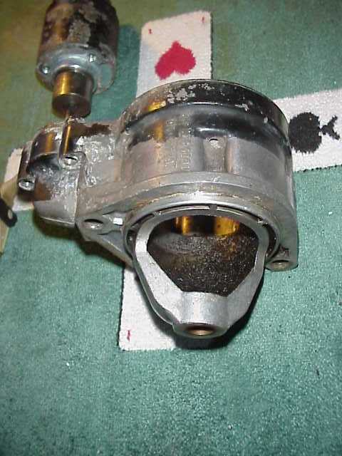
Either way, the front casing is probably in the way:
This is made of cast aluminium and is very easy to saw with a hack-saw. The complete shrouded section may be removed, in which case the phosphor-bronze bearing must be removed from it, and then must be fitted into your robot frame to support the front end of the motor. Alternatively, if the section at the very front containing the bearing is sawn in half, it may allow enough shaft to protrude so that a sprocket or gear wheel can be fitted to it.
If the whole front casing is sawn off and the bearing mounted in the robot frame, this allows the gear wheel already mounted on the motor shaft to be used as the drive wheel. However, since this can slide up and down the shaft by a couple of centimetres (the solenoid of pre-engaged starter motors simply pushes this gear wheel up the shaft to engage with the engine crank wheel), it should be welded in its protruded position (nearest the end of the shaft).
Another option is to leave the front casing as it is, and use a gear wheel with same pitch as the gear wheel on the motor shaft as the drive. The motor will need to be speed-reduced by gearing (or sprocket and chain) anyway, from anything between 3:1 to 20:1, so a gear wheel driven by the existing motor gear wheel (which has approximately 16 teeth) with from 48 to 320 teeth would provide the necessary speed reduction.