Much of the information in this page has been kindly supplied by Wakefield Engineering Inc, a supplier of all sorts of heatsinks. Click on their logo to visit their site.
If you are designing you own speed controller (see Speed Controllers), then the MOSFETs you use will need to be heatsinked so they don’t overheat. Which heatsink should you use? How big a heatsink will you need? This page attempts to help you to answer these and more questions.
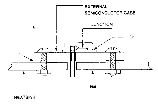
Equivalent schematic
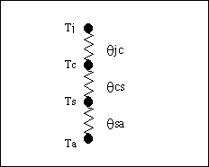
Where
![]()
Clearly the greater the heatsink surface area or convection coefficient then the smaller will be θsa. Surface area (A) can be increased either by improved heatsink design or moving to a larger version of the same heatsink.
The convection coefficient (hc) can be improved by moving from natural convection to forced convection (air or liquid).
![]()
In most applications the only unknown will beθsa. Therefore re-arranging equation 2 in favour of θsa gives
![]()
Equation 3 now enables us to consider a practical
application.
Solution: Using equation 3,
![]()
θsa = 5.9ºC/W
This is the largest value of θsa that can be tolerated. Clearly smaller values would be acceptable as these would result in a lower junction temperature.
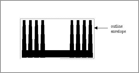
However, a shortcut would be to use Graph 1 below. It illustrates the volume of heatsink required over a range of thermal resistances for natural convection. It is not exact, as it represents the average data from many profiles, but can be relied upon to a first approximation. The volume of a heatsink is the outline envelope times the length of the heatsink:
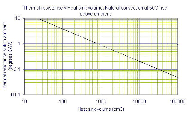
Typically, to reduce thermal resistance by 50% the heatsink volume must be quadrupled. This assumes all other parameters remain constant.
Having established a figure for the volume and presumably knowing the maximum available width and height, we can calculate the length. Alternatively, fixing any two parameters allows us to determine the third. Armed with this information, and providing it is acceptable, we can now look for a suitable heatsink profile. Clearly, under natural convection conditions and assuming no other variables, the heatsink volume must be increased to reduce θsa.
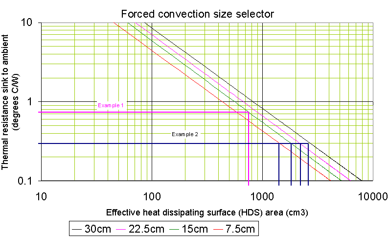
The engineering data supporting the curves is based on air movements in the laminar region (frontal velocities of 120 to 240 metres per minute) and will provide good approximations of thermal performance. As with natural convection, it is assumed that device quantity and location add no unusual heat distribution effects. Note that the outlet air temperature from the extrusion is going to be higher than at the inlet, and it is imperative that this outlet temperature never exceeds the desired maximum surface temperature of the heatsink. In fact it should remain as far below as is practical.
The rise in temperature of the outlet air is given by the equation
![]()
where
|
|
|
|
|
|
|
|
|
|
|
|
|
|
|
For more information about fans, how they work, and selecting one, have a look at http://www.electronics-cooling.com/Resources/EC_Articles/MAY96/may96_01.htm.
Consider the following examples in the use of the forced convection selector guide:
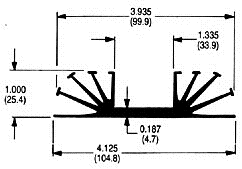
From the datasheet we see that the heat dissipating surface (HDS) is 58.17 cm2/cm. Therefore the total HDS for a 15cm length is 15 x 58.17 = 873cm2.
Locate 873 on the horizontal axis of the graph above, and move vertically to intersect the 15cm length curve and then move horizontally to intersect the vertical axis at 0.65ºC/W. This is the θsa for this example. Now let us apply some operating conditions to check for functional effectiveness.
Question:
Will the heatsink temperature at the air outlet remain below 130ºC under the following conditions:
First calculate the outlet air temperature rise:
![]()
Multiply by 45ºC correction factor:
Tcorrected = 3.2 x 1.08 = 3.45ºC
Now calculate the heatsink temperature rise:
Tsink = θsa x input power = 0.65 x 100 = 65ºC
The heatsink temperature at the air outlet is
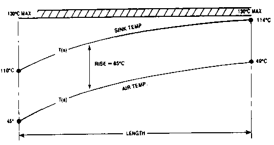
Tair + ΔTair + ΔTsink = 45ºC + 3.2ºC + 65ºC = 114ºC
This suggests that the performance will stay within acceptable limits.
To visualise this more clearly it is useful to show these temperature profiles as follows:
Because of variables associated with the length of heatsinks, we will average the information from the curve of each of the four lengths.
Locate 0.3ºC/W on the vertical axis of the graph and move horizontally right to intersect the curves and read vertically down, recording the HDS for each length:
The HDS of Wakefield 1371 extrusion is 58.17cm2/cm and the required length can be determined by simple division:
![]()
= 2150/58.17 = 40cm.
Clearly any greater length would be acceptable. For
intermediate lengths it would be reasonable to extrapolate the required
values.
|
|
|
| Wakefield thermal compound |
|
| Beryllia washer |
|
| Wakefield "delta pads" |
|
| Mica washer |
|
An excellent article about different thermal compounds that can be used to improve θcs can be found at http://www.electronics-cooling.com/Resources/EC_Articles/MAY97/article3.htm.
A more extensive list of thermal interface materials can be found at http://www.peltier-info.com/tims.html

![]()
where K is constant for the material. Therefore to keep thermal resistance low, conduction paths should be short and have a large cross-sectional area.
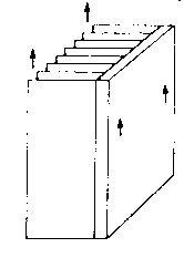
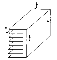
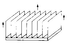
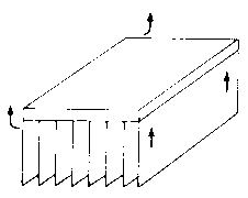
Any finned shape will have a lower thermal resistance
in forced convection than in natural convection, on account of the higher
heat transfer rate. Therefore under these conditions choose a heatsink
with thicker sections.
However, it is stressed that the performance of a heatsink is dependant on many variables such as location in the equipment, effective airflow, fin spacing, fin height, fin thickness, base thickness, shape, and overall length. Consequently the impact on the performance of a heatsink mounted other than vertically is not a fixed number, and may depend on the inter-relationship between two or more of these variables.
In general, they are not very efficient, taking large amounts of power. For more information on the Peltier effect, devices, and manufacturers, see http://www.peltier-info.com/
What size heatsink do I need - from Winnipeg Robotics Society
http://www.winnipegrobotics.com/heatsink.html
A
list of articles from Electronics Cooling magazine.
Some are interesting to us, some are a little too academic.
Here are links to some interesting articles from Electronics Cooling Magazine:
How to select a heat sink, by Seri Lee, Aavid Thermal Technologies.
Ten stupid things engineers do to mess their cooling. Interesting.
An excellent practical article on what to put between the component case and the heatsink.
An article about interface resistance between the package and the heatsink. A little mathematical, but does show what happens when silicone grease is used, and the effect of contact pressure.
All you need to know about fans.
Fan selection - quick techniques to compare various tube-axial fan designs.
An article about forced convection cooling in enclosures. Quite mathematical, but some good hints.
A very mathematical article about finding how much air flows past a heatsink without contributing to reducing the temperature. There's a table at the end with the results though, so you can ignore the maths at the top.
A fairly simple short article on one dimensional heat flow past a heatsink.
International rectifier have a few datasheets on mounting their MOSFETs, some are in Acrobat PDF format:
Mounting Considerations For International Rectifier’s Power Semiconductor Packages.
Mounting Guidelines for the SUPER-220 package.
Mounting Guidelines for the SUPER-247 package.
Estimating the junction temperature (Tj) of Power MOSFETs.
Infineon do similar documents for their MOSFETs, in Acrobat PDF format:
Thermal resistance - theory and practice. A very good booklet with practical information.
An article on modelling thermal circuits with SPICE and SABER circuit simulators - if you're into that sort of thing!
Other sites:
Flomerics produce various thermal simulation software packages, demos are available too.