V2.00 27-Jul-04
Tachographs are slightly more complicated to make than a stroboscope, since you need to attach a device to the motor that can affect an external device which then counts the number of disturbances in a given time frame. Here I present the design of a stroboscope, and describe how it can be used to measure the rotational speed of a motor, or wheel.
The types of stroboscope used to measure care engine speeds are not suitable for our purposes. This is because they do not have an independant and measurable oscillator to control the frequency of the flashing. Instead they use the ignition timing of the engine to control the flash. They are actually designed for measuring the phase angle of an object (i.e. the timing of the spark relative to the position of the camshaft) rather than the frequency of the object.
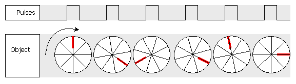
A mark is made on the object that is rotating that you wish to measure, and the object is spun up to speed. The oscillator is set to a low frequency to start with, and the LED is shone at the object where the mark is. At first, the mark will appear at random points around the object
The frequency of the oscillator is then gradually increased until the mark appears to remain stationary.
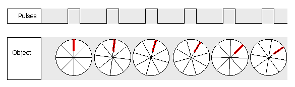
If the strobe frequency is slightly under the speed of the object, the mark will creep forward:
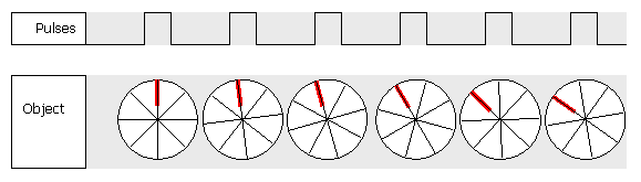
And if the strobe frequency is slightly faster than the speed of the object, the mark will creep backwards:
This is a little better shown in this web site which has animated graphics.
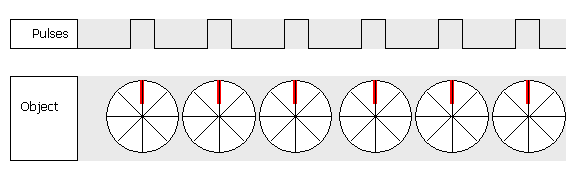
When it is stationary, the LED is flashing at the same frequency as the object is rotating. Since the frequency is known, the rotational speed is also known, and can be stated in RPM using the formula:
RPM = 60 x fstrobe
Oscillator section:
Driver section:
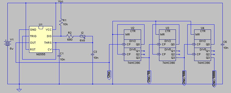
The potentiometer I2 and capacitor C3 form an oscillator with the NE555 U1. The capacitor type chosen is important (MKP 1837). This type is very stable over temperature and is of low tolerance. This enables the strobe to measure speeds within about 5% accuracy, which is tolerable for our purposes (see section 5 for a method to improve the accuracy further).
The oscillator is designed to operate over one decade of frequency, from 100Hz up to 1000Hz. This allows us to measure rotational speeds up to 60,000 RPM. The oscillator drives the counter chain (U2, U3, U4), and after each decade counter, the pulses are ten times lower in frequency.
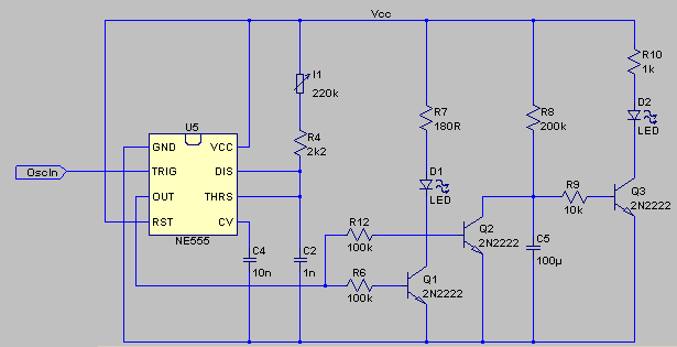
In the driver section, the LED pulse is set to a constant width. If the width was too wide, the mark on the object would look blurred. Therefore a monostable (U5) is used to generate the fixed width pulse, regardless of the oscillator frequency. At low speeds, this pulse may be reasonably wide, but at higher speeds, it must be shorter to prevent blurring (and of course it must always be less than half the oscillator period since then the LED will be permanently on). The width of the pulse can be adjusted using potentiometer I1. If it becomes too wide such that the LED is permanently on, the DC detect circuit (Q2, Q3 and associated components) causes D2 to shine to indicate this.
The frequency used to drive the monostable is selected from one of the decade counters. This is achieved using a rotary switch to select one of the signals OSC, OSC/10, OSC/100, or OSC/1000 to be fed into the OscIn signal of the driver section. The length of the counter chain, 3 stages, should be adequate for speeds down to 60 RPM, which is once per second. Speeds lower than that you can visually time the rotational speed.
The LED D1 shown in the circuit diagram is an ultrabright type. For more brightness, more than one LED may be used. In this case, use a 180 Ohm resistor in series with each LED - the LED-resistor series pair being in parallel with other LED-resistor pairs. If you want more than a couple of LEDs, then the transistor must be uprated. Use an NPN with similar hfe value but larger maximum collector current.
Drawing the dial is best achieved by writing a computer program, and printing it out. First the complete angular range of the potentiometer should be measured using a protractor. This will be something around 280 degrees. Make sure you do this as accurately as possible. Next the resistance of the pot at either end of this range should be measured using a digital multimeter (DMM). These values can then be inserted into the program below to obtain a drawing of the dial which can be printed. Note that the code is written in Borland C++Builder and uses fairly obvious drawing commands. This can be translated into whichever computer language you prefer. There is also an executable Windows version of the program. Both can be downloaded as a ZIP file here.
This program also allows you to mark the dial for RPM rather than frequency, and to generate a Vernier inner disc for the knob of the potentiometer.
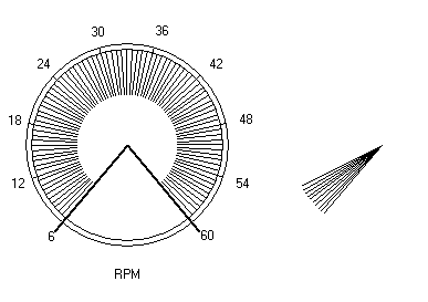
The dark lines running from the centre show the mechanical range of the pot. The scale may overrun or underrun this depending on the difference between the nominal and actual value of the pot. These mechanical limit lines can be removed by unclicking the appropriate check box.
| Switch connects to | Freq Marking | RPM Marking |
| Osc | x 100 | x 1000 |
| Osc/10 | x 10 | x 100 |
| Osc/100 | x 1 | x 10 |
| Osc/1000 | x 0.1 | x 1 |
If the dial has reached its end-stop, twist it back and turn the decade switch to its next setting. Now repeat the operation with the dial.
When the mark is shown stationary, read off the single digit on the dial, and attempt to get a second digit by estimating the distance between the two marks on the dial (this should be a lot easier if you have put the Vernier dial on too). For an example, let's say you read about 4.2 or 4.3. Now read the decade switch position, say that was "x 10". The frequency is then 4.2 times 10 which is 42Hz. The RPM is just 60 times this, which is 2520 RPM.
Rather than convert to RPM like this, you can mark the pot dial and decade switches for RPM measurement directly. For the dial, change the figures from 1-10 to 6-60, and use the markings in the third column of the table for the decade switch.
To obtain a vernier dial, also plot the Vernier dial using my program. Cut this to an appropriate size, and glue it to the underside of the potentiometer knob. Glue the other dial to the front panel of the stroboscope as normal.
It is questinable whether the manufacture of the dial, fitting of the knob on the pot, and mounting of the pot on the front panel can be done accuratley enough to justify a Vernier scale, but it is a nice touch anyway!
A solution to these problems is to measure the frequency of the oscillator directly using digital electronics. I present here four different methods of measuring the frequency of the stoboscope rather than reading it off the dial. Some are easier than others, and some are cheaper than others!
 Click on the circuit diagram to open it in a new window
Circuit description
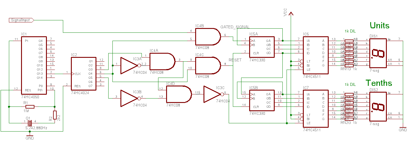
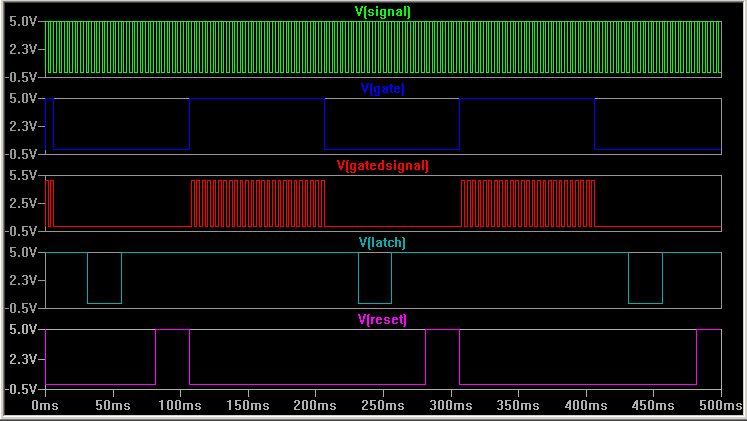
The crystal frequency is divided down by IC1 and then IC2 to generate a pulse 100ms wide. This is used to gate the signal to be measured by IC4b. The number of pulses in this gated signal are then counted by the two decade counters IC5a and IC5b. The output of the counters are latched into the 7-segment display drivers IC5 and IC7 by a latching pulse which follows the gating signal. The counters are then reset by a pulse that follows the latching pulse.
The SPICE simulation waveforms are shown below for a signal frequency of 250Hz. The gated signal includes 25 pulses.
An alternative to using this digital frequency meter is to build the Velleman kit K2625. This is available from Maplin code number VE01B for £25.
| Manufacturer | Device |
| Maplin electronics | Rotary switch |
| 7-segment LED display | |
| Vishay-Roederstein | MKP 1837 1% polypropylene capacitors |
| Fairchild Semiconductor | NE555 oscillator |
| 2N2222 NPN general purpose transistor | |
74HC04 Hex inverter |
|
74HC08 Quad AND gate |
|
74HC390 Dual decade counter |
|
74HC4024 Dual 4-bit binary counter |
|
74HC4511 BCD to 7-seg decoder |
|
74HC4060 14-bit counter/oscillator |
|
| Kingbright | Ultra-bright LED |
| Meggitt Piher | PC16 Potentiometer |
| Maxim | ICM7224 Frequency counter & display driver |
| Varitronix | VI-509-DP-RC 4½ digit LCD module |
[C2] A commercial stroboscope using a zenon lamp instead of LEDs
http://www.sestechno.com/pro1/4p.htm
[E1] A description of what a stroboscope is and example applications
http://www.fda.gov/ora/inspect_ref/itg/itg12.html
[E4] An excellent tutorial on stroboscopes with good animation, explaning the history, and
operation of a stroboscope.
http://web.mit.edu/6.933/www/Fall2000/edgerton/www/stroboscope.html
[E1] EPE magazine LED stroboscope construction project. Search for 'stroboscope' in the listings (Have to pay for it, hence score of [1]!)
http://www.epemag.com/projcat.html