V1.04 2-Jan-2002
Testing status: Simulated
This circuit takes the output of a radio control receiver channel, and drives a load on or off dependant upon the value on that channel. Generally, a channel can transmit a range of values, and a sercvo is used to position a motor dependant on the value sent over that channel. However, for applications such as a weapon, a simple on/off action is all that is required.
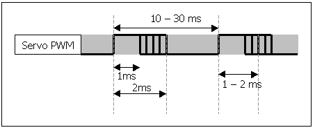
Let's first have a look at the output signal of the radio receiver:

A positive-going pulse is sent at regular intervals, at most every 30ms although some manufacturers have a maximum of 20ms between pulses. The width of the pulse is between 1ms and 2ms. If a servo was attachjed to this, a 1ms pulse would cause it to turn to its minimum extremity, and a 2ms pulse will cause it to turn to its maximum extremity. The range is linear, which means the centre-point the servo position is achieved by sending 1.5ms, halfway between 1ms and 2ms.
We want the output of our circuit to be OFF when the received pulse width is less than 1.5ms, and ON when it is greater than 1.5ms (or vice versa, it doesn't really matter).
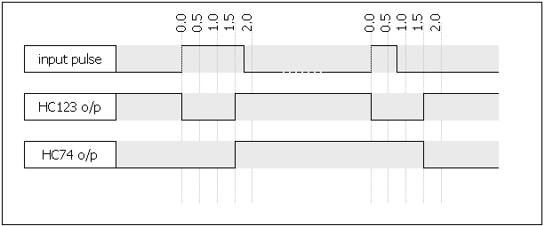
The "retriggerable" part of its name means that if another pulse arrives while it is still generating its output pulse (i.e. less than 1.5ms after the first input pulse) the output will still last 1.5ms after the most recent input pulse. For our purposes, that action is irrelevant since the input pulses will arrive at least 20ms apart.

A timing diagram for the action of this circuit is shown below. two input pulses are shown, one longer than 1.5ms and the second shorter. The first causes the DFF output to go high, and the second makes it go low.

The width of the output pulse of the monostable is determined by the resistor and capacitor values, and is simply
t = 0.45 × R × C
To make the 1.5ms as accurate as possible, it is recommended to use 1% tolerance resistors and capacitors. Vishay make a range of low-tolerance capacitors (see parts list at the bottom of this page). 1% resistors are easy to come by. The diode across the resistor (D1) is to prevent excessive currents in the chip.
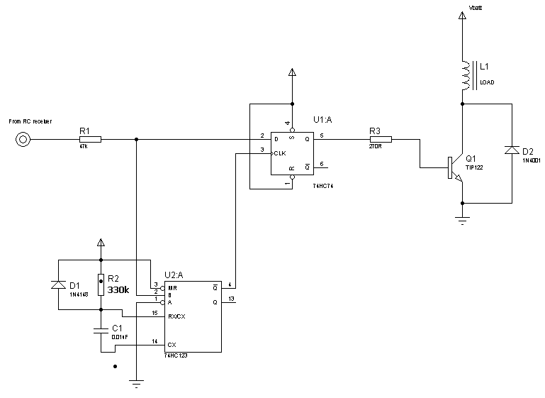
Now we have a threshold event - the rising edge of the monostable output. The required circuit output state will be captured in a D-type flip-flop (74HC74). This has an input, D, an output Q, and a clock control input. Every time the clock control goes high, the value at D is transferred to Q. The clock control going low has no effect. If we connect the threshold event signal to the clock control input of the D-type flip-flop, and the pulse from the radio control receiver to the D input, then at the event threshold, the radio control receiver signal will be "sampled" by the flip-flop, and its value set at the Q output.
Surrounding the monostable and flip flop, there is some interface circuitry. To protect the inputs of the logic chips, a series 47k resistor is used (R1). The signal from the radio control receiver may be a higher voltage than the logic chip power supply. The logic chips have internal protection diodes to limit the input voltage to the supply range, and the series resistor limits the current in these protection diodes.
At the output of the circuit, I have added an on/off load driver circuit. This uses a Darlington transistor (a very high gain dual-transistor), Q1, which turns on when the output of the flip-flop is high. The Darlington turning on allows current to flow through the inductive load (motor or solenoid for example) at the output, thus activating it. Note that the diode (D2) across the Darlington may be required to recirculate decaying current caused by the possible inductance of the load - it is a freewheeling diode just like the ones used on H-bridges in speed controllers (see description here in section 6). However, the TIP122 incorporates a diode for this purpose, which should be adequate for smaller, less inductive loads. This Darlington is good for loads up to about 8A.
How did I calculate the series base resistor value? Looking at the TIP122 datasheet, it tells us that the minimum gain of the transistor is 1000. Therefore, when the collector current is 8A, the base current will be 8mA. (8A / 1000). Also, the datasheet tells us that the Vbe (voltage from base to emitter) when the transistor is fully on is about 2.5 Volts. Therefore, the resistor must drop 2.5V (5v at the 74HC74 output down to 2.5V at the transistor base) when passing 8mA, so the resistance is 2.5 / 8mA = 312 Ohms. 270 allows for some leeway to ensure the transistor is fully switched on. The actual current drawn from the 74HC74 will be 2.5 / 270 = 9.25mA which the 74HC series is capable of sourcing (absolute maximum is 25mA).
An alternative to using a Darlington would be to use an N-channel power MOSFET. However, this must be a logic level MOSFET because the gate will only be driven as high as 5v by the logic chip. The 270 Ohm series resistor should be maintained to limit the current draw from the 74HC74 output when the gate is turned on and off. This will slow down the MOSFET switching, but this circuit is only switching at low speeds anyway.
Note that both the 74HC123 and 74HC74 are dual devices. Therefore you can easily make a dual channel switch simply by adding a second series resistor (R1) and driver section (Darlington pair). If you do not want another channel, make sure that the unused inputs are all tied to inactive states (tie them all to Vcc), otherwise they may oscillate causing much higher current consumption. Just leave unused outputs open.

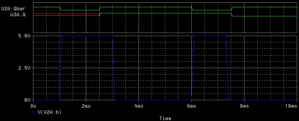
For more information on SPICE and circuit simulation, see my SPICE page.
The following devices are used in this circuit. Click on the device name to go to the datasheet. Click on the manufacturer’s name to go to their website.
| Manufacturer | Device and datasheet link |
| Vishay-Roederstein | MKP 1837 1% polypropylene capacitors |
| Philips Semiconductor | P74HC123 monostable |
| P74HC74 D type flip flop | |
| Fairchild Semiconductor | TIP122 Power NPN |
| 1N4001 1A diode | |
| 1N4148 Signal diode |
1. I have found a similar circuit to this here, which uses half of a 4000 series CMOS D type flip flop as the monostable, and the other half as the sampler. This is quite cool (only uses one IC) but may suffer from the following problems:
2. Some other RC switch projects are:
http://www.focalpoint.freeserve.co.uk/anvil/how2rc_switch1.htm
http://www.welwyn.demon.co.uk/rcsw/rcsw.htm
http://www.tuug.fi/~isaarine/electronics/rc-switch/
3. Radio controlled switches are available commercially. Here are the sources
that I have come across:
Powertrac (UK)
Team Delta