Testing status: All circuits tested
Introduction
Many of the circuits in this section show various power supply voltages, and some refer to "use the opamp negative supply" for example. Where can we get these voltage supplies from?
We only want to use one battery for all the low-power electronics. It is important that we do not use the motor power battery for the electronics. The reason for this is spelt out plainly in the EMC section here. All the electronics supply voltages we need must therefore be derived from the electronics supply battery.
We will use a voltage regulator to generate the _5v for the logic, and a switched capacitor voltage converter to generate the positive and negative supplies for the opamps and other linear circuitry.
Why do we need a voltage regulator to supply +5v when a 6v battery should be close enough?
Logic chips generally require a very stable +5v supply. The high speed CMOS family 74HC requires a supply between 2V minimum and 5.5V absoulte maximum. Running this at 6v is likely to damage the ICs. Secondly, the regulator is able to respond to small fluctuations in the input voltage caused by other loads off the same battery switching on and off. It guarantees a +5v output signal as long as its input is a certain voltage above 5v (called the drop-out voltage), and the load on it is not too high. Single chip voltage regulators are available with a range of output current capabilities, from 100mA up to 5A and higher. For our purposes, using 74HC logic at relatively low frequencies, a 1 Amp regulator should be easily sufficient.
This document refers to the National Semiconductor LM340 series of voltage regulators, although many manufacturers supply fixed voltage regulators, many with the part number 78iVV where "VV" is the output voltage, and I is a code letter for the maximum supply current. For example 78L05 is a 100mA +5v regulator. 7812 is a 1Amp 12V regulator.
A circuit diagram of the regulator feeding directly off the battery supply is shown below:
The regulator consists of a series pass transistor, and a feedback control circuit. It continuously monitors its output voltage, and compares it with a fixed voltage reference (+5V in this case). If the output voltage rises as the load current falls, it turns the pass transistor off slightly more. As more current is drawn, the voltage at the output of the regulator will start to drop, and the regulator will turn its pass transistor on slightly more to keep it up to +5v.
The capacitor between the battery and the regulator is required to ensure there are no high frequency variations in the supply to the regulator. The capacitor after the regulator is required to supply high frequency variations in the current drawn by the logic chips, which the regulator is not fast enough to react to.
If more current is required, then there are two simple options. One is to use a higher current regulator - up to 5A regulators are available. Another is to use the circuit shown below:
In this circuit, the transistor Q1 is used to share some of the current supplied. The voltage regulator maintains the output voltage, and still operates short circuit protection. The current that the transistor takes is set by the resistor values R1 and R2, and is I = R2/R1 * RegulatorCurrent. The example shown converts a 1A regulator into a 5A (4A for the transistor plus 1A for the regulator) voltage regulator circuit. See the LM340 datasheet for a full description of this circuit.
The following SPICE simulation shows how the current is shared between Q1 and the regulator (U1) as the load current increases from 0 to 5 Amps. The regulator in this simulation has a short circuit current of 1.6A.

Linear opamp circuits often need a negative supply rail as well as a positive to allow their input and output signals to go all the way to 0v (and certainly if they need to go below 0v). Most opamps (although not all) will not swing their outputs to the positive and negative supply rails (this would require output transistors that have a zero voltage drop across them when they are turned fully on). Many also do not work when their input signal voltages are at either supply rail.
If we keep our linear circuit voltages around the +/- 5V range, then opamp supplies at +/- 10V will be perfectly adequate.
How can we generate a negative voltage from a positive one? This is achieved by a clever circuit called a switched capacitor voltage converter. The diagram below helps to show how it works:
It charges up a capacitor to the input voltage by connecting the capacitor Ca directly across the input voltage (a). This capacitor then has a top plate charged to Vb volts above its bottom plate.
It then disconnects this capacitor, and reconnects it as shown in (b). Now the bottom plate, which is still Vb volts below the top plate, must be at a voltage of -Vb. Ca dumps its charge into Cb, and the bottom plate of Cb will tend towards -Vb (each charge dump will not dump all the Ca charge into Cb).
This switching process is repeated at high speed. Note that you can’t pull a large amount of current from these supplies because the energy is just stored in the capacitors, but they are perfectly adequate for low-power opamps.
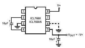
The switches and control circuits are all integrated into one IC. The one we use here is the ICL7660. This can be configured in a variety of ways so it can supply a voltage double that of the incoming voltage as well as a negative one. This is ideal for us to generate +10V and -5V from the single +5v regulated supply we have already created. -5V should be adequate for most of the circuits presented here. If not, multiple ICL7660s can be used to generate +10V from the +5V, and then -10V from the +10V. See the datasheet for the ICL7660 for examples of circuit configurations to realise these voltages.
The presence of the diodes means that this circuit does not generate quite double the input voltage, it being two diode drops voltage below that, so we can still generate +8.6V or so from the +5V input.
A negative supply circuit is shown here:
The ICL7660 datasheet shows waveforms for the pins of this chip.
This chip can also generate double the input voltage, or both double and negated voltages:

The values of the capacitors are not very important, but must be all the same. 10uF is reasonable.
An application note describing many different circuits using the ICL7660 can be found here.
The following devices are used in this circuit. Click on the device name to go to the datasheet. Click on the manufacturer’s name to go to their website.
Manufacturer |
Device and datasheet link |
| National Semiconductor | LM340T-5.0 voltage regulator |
| Intersil | ICL7660 voltage converter MAX1044 voltage converter |
| Maxim |