These sensors, commonly called mercury switches (although few now contain mercury) work by containing an electrically conductive fluid inside a sealed bath. Contacts at strategic points are either connected or broken by the movement of the fluid.
The problem with using a mercury switch on a fighting robot is that it is likely to trigger often during a bout due to the liquid sloshing around when the robot is struck by an opponent, or makes a violent maneouver. Therefore, the signal from the switch must be suitably filtered by either hardware or software to obtain a signal that will only trigger when the robot is definitiely inverted.
I will describe some simple hardware methods of performing this filtering, along with some software methods also. The software methods are obviously only suitable for robots with on-board microcontrollers. The filter must be a low- pass type, whatever the form of its implementation, since it is the low frequency element of the signal that is required, and the higher frequency ‘sloshing’ signal that we want to filter out.
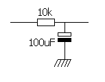
A low pass analogue filter can be contructed from a single resistor and capacitor connected as shown below.

This circuit has a frequency response described by the following equation:

where f is the frequency of the signal. One of the characteristics of a filter is its 3dB point. This is the frequency at which the signal is 3 decibels lower, which is half of its input value. This is also callled the cutoff frequency. The 3dB point of the filter shown above is

Therefore, if we want to filter out signals above 1Hz, we can set the 3dB point to 1Hz by choosing values for R and C appropriately, for example, R=10kΩ, C = 100uF.
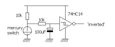
The output from this filter will be a slowly changing waveform. This can cause problems when presented to other circuits, since a little noise on top of a slowly changing signal can cause comparators to oscillate at their outputs at the state change point. This can be fixed by placing a device with hysteresis at the output of the filter. A suitable device is a Schmitt input logic device. The following circuit shows the mercury switch, filter, and Schmitt device together to generate a suitable ‘inverted’ logic signal:
A simple method of gettiing a true ‘inverted’ logic signal can be obtained using a digital shift register and AND gate as shown below:
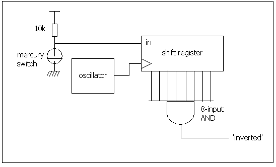
In this scheme, the shift register ‘samples’ the state of the mercury switch at regular intervals (determined by the oscillator). Only when 8 consecutive samples are all at a ‘1’ state, will the output change over. The frequency of the oscillator determines the effective cutoff frequency ofthis type of filter. For example, if we require that half a second of stable signal is required, then we set the frequency of the oscillator such that 8 samples are taken in 0.5 seconds, so

There is a chance with this circuit that the input could still be changing, but the eight samples all just happened to occur when the mercury switch was in the same state.
The circuit above can be obtained in a single chip solution, designed for debouncing switches (which is effectively what we are doing). For example, the Motorola MC14490
integrates six 4-bit shift registers with a slightly cleverer connection than that above.
The shift register method is exactly the same as that described above in the digital hardware method. The switch is sampled at regular intervals, and if a sufficient quatity of the incoming samples are TRUE, then the state is assumed to be TRUE:
|
code fragment 1 This function reads the mercury switch input state, and adds it into a
shift register. The shift register is then examined, and a response returned
based on its contents.
#define SHIFT_REG_SIZE 8
|
Digital filtering is a part of the realm of Digital Signal Processing (DSP). This can be performed using simple microcontrollers – discrete DSP processors are not necessarily required. For an example like this, where the sampling is slow, and the response is not needed particularly quickly, a normal microcontroller is perfectly adequate.
I will not describe how digital filters work at all here – that is far too large a subject, as a search on a search engine for "digital signal processing" will testify! I suggest you perform that search if you are interested!
Below is a block diagram of a 5-tap FIR digital filter which will perform well in this application. This filter will have a performance similar to a 5- pole analogue filter – the RC network in section 2.1.1. is a single pole filter, but FIR filters do not have ‘poles’ as such.
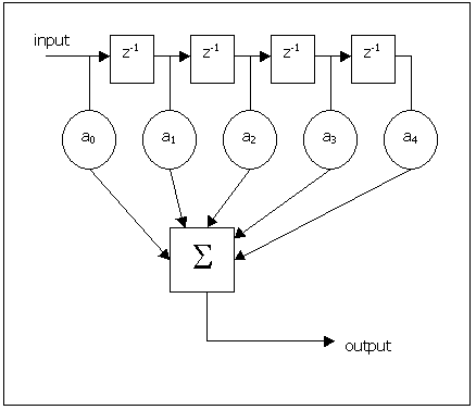
The boxes marked z-1 are single delays. That means that their outputs are just the value of their inputs delayed by one sample time. The circles are multipliers – for example the first one multiplies its input by a 0 to get its output. The outputs from the multipliers are all added together to the output signal.
If the input signal is called x(t) where t is time, then x(0) is the first value of the signal, x(1) is the value one sample time later, etc. The output we’ll call y(t). We can then write:
y(t) = X(t).a0 + X(t-1).a1 + X(t-2).a 2 + X(t-3).a3 + X(t-4).a4
The values of a0 to a4 are determined by mathematical methods common to DSP. This is described here if you are interested.
Example code for performing this digital FIR filter is shown below:
|
#define FILTER_SIZE 8
|
In practice this code could be much improved (for example by using a circular buffer for the sample values), but this is only to illustrate the point.
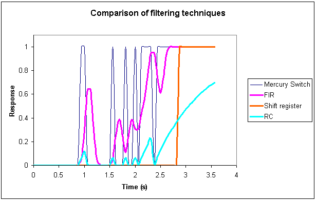
To get some idea how these methods perform, there is an example signal from a mercury switch, and the resultant outputs from the filters shown in the diagram below:
A plot can be made of the RC and FIR filters attenuation versus frequency. This shows how quickly they "drop-off" as the frequency increases:
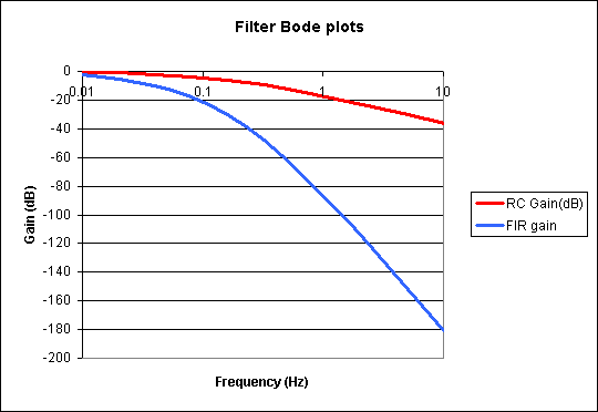
In practice, the FIR digital filter would probably have a lot more taps, which would improve its performance immensely. The RC filter can be seen to have a very slow response when the correct signal comes. This is because its drop-off with frequency is very slow, attenuating by an extra 20dB for every decade in frequency (20dB = 2.7 times when frequency increases 10 times), whereas a 5-tap digital filter will drop-off at 100dB per decade (148 times). The shift register methods are not regular filters and so do not have a drop-off in that sense.
So which method is the best? Since this is not a particularly demanding application, the simple RC filter should work perfectly adequately. If you have a microcontroller on board, then the software shift register method should be adequate. It is unlikely that you will need to go to a digital filter for such an undemanding application.
The following devices were mentioned in this article. Click on the manufacturer’s name to go to their web site, or the device name to go to the device datasheet.
Manufacturer |
Device |
MC14490 switch debouncer |
|
74HC14 Hex Schmitt inverter |
|
Mercury/tilt switches |
Switch debouncing using a 555 timer IC
http://www.mitedu.freeserve.co.uk/Circuits/Switching/debounce.htm
An article showing several circuits for switch debouncing
http://www.mitedu.freeserve.co.uk/Design/debounce.htm