Microswitch |
Optical detector |
Magnetic reed switch |
V1.01 22-Dec-05
If you have a weapon or mechanical actuator on your robot which is driven by an electric motor, the weapon will probably have an allowable range of travel, and outside that range, it will be desirable to turn off power to the motor to prevent the motor burning out, or unnecessary wastage of battery power. This page describes how this can be achieved.
The idea is to use detectors to detect the extremity of travel, and use the signals from these detectors to control the allowable direction that the motor can be driven in:
Detectors |
Weapon position | Allowable motor direction | |
| Fully up | Fully down | ||
| û | û | In allowable range |
Both |
| ü | û | At top of range |
Downwards only |
| û | ü | At bottom of range |
Upwards only |
| ü | ü | At least one detector is faulty | |
The motor must be able to be driven in both directions, which tells us that an H-bridge arrangement must be used. A detailed description of H-bridges can be found in the speed controller page.
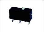
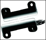
The simplest form of detector to use is microswitches. More reliable methods would be to use optical, or magnetic detectors such as those in the pictures below. Click on the pictures to see the technical details of each:
Microswitch |
Optical detector |
Magnetic reed switch |
The use of these will be described later in this page, but for simplicity in understanding the theory, we'll use microswitches initially.
The circuit diagram of an H-bridge weapon motor controller with the extremity limit switches in place is shown below:
This shows the motor driving a "stick" weapon which can travel up and down between the two microswitches. The H-bridge is made from two SPDT relays. These must be capable of switching the maximum motor current. There are 2diodes (across the relay switch contacts) that are also capable of taking this current, and two much smaller diodes across the relay coils. The diodes are for current freewheeling which is described on my web page on speed controllers. The motor takes the same voltage as the battery supplies, and the two relay coils are also selected to operate at this voltage.
When the weapon arm is in between the extremities, both microswitches are conducting, and the motor may be driven forwards or backwards (resulting in the arm going up or down) by pulling the control lines marked UP and DOWN down to ground (Gnd). When Gnd is applied here, the appropriate relay coil is energised, and its contacts switch over.
The circuit diagram is shown with the "UP" control input pulled low, relay 1 energised, current flowing through the motor from left to right, and the arm driving upwards. When the arm reaches the upper extremity of its travel, the upper microswitch will open and relay 1 will be de-energised. The relay 1 contact on the left hand side of the H-bridge will toggle and the motor will come to a stop. Freewheeling current is then allowed to circulate around the lower loop of the H-bridge (for details of freewheeling, see my speed controllers web page).
With the upper microswitch pushed, the only way the motor can now be moved is in the downwards direction. Releasing the "UP" control input and pulling the "DOWN" input down to Gnd energises relay 2, and current now flows through the motor from right to left, and the arm is driven downwards. When it reaches it's lower extremity, the lower limit switch contact opens, and the motor can no longer be driven downwards.
The motor cannot be forced to stay in one position - when de-energised, any torque applied to it from the weapon arm will cause it to rotate. However, if when the arm reaches the upper extremity for example, the Vbatt on the "UP" input is left there, the microswitch contact will open, the motor will be denergised, the arm will fall slightly due to gravity or reverse torque from the arm, the microswitch will open again, and the motor will be re-energised driving the arm up again. Therefore the arm will "wobble" about near the upper extremity, which will effectively hold it in place in this position.
The circuit diagram above shows the relays activated by a voltage at Vbatt. These inputs will take a reasonable current (the current of the relay coil which may be a few hundred milliamps), and are not "logic-level" compatible. If you want to drive these with logic level inputs, use two channels of a ULN2003 relay driver IC:
The above example used relays to drive the motor. This is OK for fairly small motors, but if a large motor is to be driven, it is better to use MOSFETs since these can generally switch higher currents more reliably than relays, and have integral reverse-diodes for freewheeling. An equivalent circuit diagram to the relay version is shown below:
This uses the new ST TD340 H-bridge driver chip. The IN2 input is the direction input. For details of the use of this IC follow the link to the ST page.
For details on other aspects of the H-bridge circuit, e.g. series gate resistors, MOSFET behaviour, MOSFET intrinsic diodes etc, see the speed controllers page.
The direction signal is dependant on the state of the lines from the limit switches however, using the logic gates shown. The signals from the limit switches rise to Vbatt, so the series 47k resistors limit the current that will flow through the protection diodes in the input stage of the logic chips. This is a common and allowable method of driving 5v logic inputs from higher voltages.
These gates combined have the following truth table:
Dir in |
UP |
DOWN |
Dir Out |
0 |
0 |
0 |
0 |
1 |
0 |
0 |
1 |
0 |
1 |
0 |
0 |
1 |
1 |
0 |
0 |
0 |
0 |
1 |
1 |
1 |
0 |
1 |
1 |
0 |
1 |
1 |
x |
1 |
1 |
1 |
x |
In this table, for Direction, '1' represents up and '0' down. The limit inputs are '1' when they are limiting, and '0' when they are not active. The truth table is redrawn in Karnaugh map form:
| Dir | LimU:LimD |
|||
| 00 | 01 | 11 | 10 | |
0 |
0 | 1 | x | 0 |
1 |
1 | 1 | x | 0 |
The Karnaugh map identifies a central block of four which equates to [LimD], and a lower left block of two which equates to [/LimU · Dir]. Therefore the complete logic equation for the direction input ot the TD340 is:
IN2 = LimD + [/LimU · Dir]
For implementation, this can be achieved on one 74HC00 quad NAND gate by rearranging the equation with intermediate variables ND, NU, and RD as follows:
ND = /LimD = /(LimD·LimD)
NU = /LimU = /(LimU·LimU)
RD = /[NU · Dir]
IN2 = /[ND · RD]
The following devices were used in this circuit. Click on the manufacturer’s name to go to their web site, or the device name to go to the device datasheet.
| Manufacturer | Device | Supplier |
Code |
| NAIS | JW2SN-DC12V 5A Relays | RS | 178-2129 |
| Saia-Burgess | XC Microswitch | RS | 301-2472 |
| Optek | OPB360 Optical slotted detector | RS | 303-1192 |
| Comus | MPS4452S Magnetic reed switch | RS | 361-4949 |
| Fairchild | IRF540 MOSFET | RS | 244-9536 |
| International Rectifier | IR2110 MOSFET driver | RS | 395-4584 |
| ST | TD340 H-bridge driver | Anglia | TD340ID |