It has been stated in other pages on this website that it is a very good idea to have two separate batteries, one for the drive (weapons and wheels), and one for the radio control receiver and other electronics (see Speed controllers and EMC sections). It is very useful to know the state of charge of both of these batteries so that you do not go into a bout with uncharged batteries, but do not have to continually charge them when they are already charged (which can degrade the batteries).
This page describes two methods of determining the state of charge of the batteries.
The first is measuring the terminal voltage. This is adequate for lead acid batteries, where the terminal voltage falls off with a slight slope as the charge diminishes. However, for NiCd or NiMH batteries which are often used in the receiver and electronics sections, the discharge curve is almost flat, so the terminal voltage tells you little about the state of charge of the battery until it is just about to fail:
We can see from the discharge curve of the lead acid battery, that if we compare the terminal voltage with a fixed value of about 1.75V per cell (10.5v for a 12v battery, 21v for a 24v battery), we will get an idea of when the battery is in its terminal decline point. Note however that the discharge curves depend on how much current is being drawn from the battery at the time. This is because while drawing current, there will be a small voltage drop across the internal resistance of the battery. Hence at large current drains, the battery monitor may indicate a flat battery when it is actually OK. Therefore the monitoring should only be done (or only taken notice of) when no current is being drawn from the battery.
The voltage of the lead-acid reaction when fresh is typically around 2.15v per cell. A further comparison threshold can be put at around 2.0v per cell (12v, 24v) to indicate that the battery is down to about 25% charge left. These limits are a bit arbitrary, so we should allow them some trimmability.
A circuit diagram of the battery monitor is shown below:

The comparators are powered from the battery itself, so to get a battery voltage input which isn’t at the same value as the comparator supply (comparators would not work well like that), the battery voltage is divided by the trimmer resistors. This is compared with a value generated from the precision voltage reference. Opamps are used for the comparators since no pullup resistor is then required (comparators generally have open-collector/open-drain outputs which require a pullup resistor to make wired-OR functionality easier. They are also normally much faster then opamps at comparing, but we do not require any speed, or the wired-OR function).
The oamp after the trimmer and the opamp after the precision voltage reference are connected as buffers, and are there to ensure that the trimmer and reference do not have to supply any reasonable current which would affect their output voltages.
The 2.0V comparator LED is connected to the output of the 1.75v comparator. This ensures that when the battery voltage falls to below 1.75v and that comparator’s output goes low, the 2.0v LED will extinguish, and only the 1.75v LED will be lit. The series resistors on the LED should have the value
So would be 1kW for a 12 volt battery.
The terminal voltages vary slightly from battery to battery, so the monitor should be calibrated for your battery. For example, the following graph shows the terminal voltage of the Sonnenschein Dryfit range (per cell) given its state of charge in percent. Note that there is a range of values of around 0.1 Volts for the terminal voltage:
However, if the battery starts off with a high terminal voltage, say 2.20v per cell as in the diagram, then it will have a higher voltage at 25% (2.05v per cell in the graph). Therefore the trimmer need only be set based on the terminal voltage of the battery when fully charged. Note also in the graph caption that the battery has been left 24 hours after the state of charge has been attained. This is because the chemistry takes some time to settle.
First determine how many series cells your battery has. This is its nominal terminal voltage divided by 2. So a 12v battery has 6 cells, a 24v battery has 12 cells, etc.
N = Vnom ÷ 2
Now fully charge your battery, leave it for preferably 24 hours to stabilise, then measure its terminal voltage, Vfull. Now attach a digital multimeter to the test point TP1 shown in the circuit diagram, and adjust the trimmer until the voltage is
VTP1 = Vfull ÷ N
The following waveform shows the LED currents as the battery terminal voltage decreases along a typical discharge curve. The voltages at the other comparator nodes are also shown:
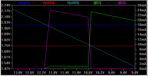
This shows that as the battery voltage falls, first D2 comes on (its current rises to 20mA), then as the battery voltage falls further, D1 comes on instead. D1 should stay lit until the battery voltage is very low (less than 3 volts) but it will get dimmer.
The alternative method of knowing the state of charge of the battery is to measure how much energy is put into it during charging, and how much energy is drained from it when it is in use. This is sometimes called "Gas Gauging", or "Fuel Gauging". A typical battery (that is not defective or worn out) will need 105% to 115% of charge put back into it to recover it to 100% charged. By knowing this and measuring the discharge and charge currents, the state of charge can be calculated.
This is rather complicated to do, and so several IC manufacturers have come up with individual Ics to do the job. These are generally mixed mode chips, with digital circuitry containing registers to count the charge rates. A selection is shown in the table below:
Manufacturer |
IC |
Comment |
| Texas Instruments | bq2010 | Integrates current measurement plus charge counters and timers. |
| bq2018 | ||
| bq2019 | ||
| bq2023 | ||
| Maxim | MAX1660 | Includes overcharge and S/C protection |
| MAX1780 | ||
| Nat Semi | LM3822 | No external shunt resistor required. |
| LM3824 | ||
| Dallas Semiconductor | DS2438 | Dallas is now part of Maxim |
| DS2760 |
These are all quite similar Ics. A sense resistor (external or internal to the IC) is used to measure the current in both directions (charge and discharge). The IC monitors this and increments the appropriate internal register (charge register or discharge register) at the appropriate rate, governed by the magnitude of the current. These registers are readable from a microncontroller connected to the IC. All the Ics in the above table have a serial link to connect to the microcontroller. This can be driven from either a serial port on the microcontroller, or just normal I/O pins. The data protocol and internal registers differ from manufacturer to manufacturer.
I have not included more details of using these Ics since I have not yet implemented this function on my robot. However, the datasheets include copious detail of how to connect the chips up, and how to communicate with them from a microcontroller.
The following devices were used in this circuit. Click on the manufacturer’s name to go to their web site, or the device name to go to the device datasheet.
Manufacturer |
Device |
Supplier |
| National Semiconductor | LM324 quad opamp | |
| LM385-ADJprecision reference | ||
| Welwyn | 0.1% precision fixed resistor1k | RS part no 165-769 |
| 0.1% precision fixed resistor 6k98 | RS part no 166-576 | |
| Spectrol | Multi-turn cermet pot (model 74) 10k | RS part no 183-3081 |
Texas Instruments:
Maxim Semiconductor:
Evaluating Accuracy of Coulomb-Counting Fuel-Gauging Systems